Vacuum excavation apparatus having an improved air lance, air lance nozzle, and vacuum system including a multistage venturi ejector

a vacuum system and vacuum technology, applied in the field of vacuum excavation equipment, can solve the problems of local fracturing of soil, rapid release of expanding high pressure air trapped within the soil, and difficulty in maneuvering shovels, etc., to achieve the effect of reducing initial costs, reducing maintenance costs, and reducing maintenance costs

Inactive Publication Date: 2005-11-15
UTILISCOPE CORP
View PDF21 Cites 11 Cited by
  • Summary
  • Abstract
  • Description
  • Claims
  • Application Information

AI Technical Summary

Benefits of technology

[0014]It is accordingly an objective of the invention to provide an improved vacuum excavation system having greater versatility, lower maintenance, and lower initial costs than conventional vacuum excavation systems.

Problems solved by technology

Essentially, application of supersonic jets of air causes local fracturing of the soil and rapid release of expanding high pressure air trapped within the soil at the local fracture sites.
The fracturing and gas-release properties of the soil are not shared by man-made structures buried within the soil, such as natural gas lines, water pipes, sewer lines, and the like, and thus these structures are unaffected by the supersonic air jets.
In addition, the use of a high vacuum for material collection causes an effective evacuation of solid material from difficult to reach areas such as beneath or behind pipes, where shovels cannot fit or are difficult to maneuver.
Despite these advantages, however, the conventional vacuum excavation systems have a number of disadvantages that have prevented their widespread use.
On the air lance side of the apparatus used in the conventional systems, the disadvantages include difficulties in handling the air lance, which conventionally must be “bounced” up and down to loosen layers of soil across an area of the excavation, and the need for a larger air supply than is available from the type of air compressor commonly used by contractors to operate pneumatic equipment.
On the material collection side of the conventional vacuum excavation apparatus, the disadvantages include both the high initial cost of the vacuum generating equipment, and high maintenance costs.
One of the reasons for the large air consumption on the air lance side of the apparatus is the low resistance provided by the conventional cylindrical nozzle or pipe nipple.
Because of this problem, nearly all companies currently performing vacuum excavation are forced to use high volume (100 cubic feet per minute (cfm) or greater) high pressure compressed air for soil breakup.
Since the most commonly available compressor has a rating of 185 cfm, the conventional cylindrical air lance requires the full power of the compressor, leaving the compressor unavailable for use as an air supply for a vacuum system, or to power other equipment, thus necessitating a separate engine driven vacuum pump.
On the vacuum collection side of the conventional vacuum excavation apparatus, most vacuum excavation systems employ vacuum pump and engine systems that require use of positive displacement blowers and various stages of filtration or cyclonic separation between the collection container and the positive displacement blowers, as the blowers are very susceptible to internal damage from particulates passing into the motive sections.
In addition to being expensive and difficult to maintain, such systems are difficult to transport, and generally can only effectively access locations less than 25 feet from the vacuum source.
The V-belts, filters, and internal combustion engines associated with vacuum pump / engine systems require complicated maintenance, which is compounded by the typically dirty and dusty work environments in which they are used, with those systems utilizing truck mounted hoppers being especially difficult to clean.
In addition, conventional excavation systems of this type have poor water handling capabilities, since water can contaminate the vacuum generating equipment and especially the filters.
Such systems can obviously not be taken indoors or up to work zones in high rise buildings.
While systems have also been proposed which use venturi-type ejectors to generate the vacuum and thereby reduce maintenance costs by eliminating the need for complex filtration or cyclonic separation systems, the conventional venturi systems require high air volumes (450 CFM or more) to generate an effective suction, and therefore require the use of large high cost air compressors and high volume connection hoses, which negates the advantage of simplicity offered in theory by the venturi engine concept.
The ultimate effect of these disadvantages is that, in order to begin using a conventional vacuum excavation system, an initial investment of greater than $100,000.00 is required, with significantly increased operating costs to be expected during the life of the system.
This puts the cost of vacuum excavation apparatus out of reach of virtually all private contractors, not to mention others who might benefit from an inexpensive air lance and material removal system.

Method used


Image

  • Vacuum excavation apparatus having an improved air lance, air lance nozzle, and vacuum system including a multistage venturi ejector
  • Vacuum excavation apparatus having an improved air lance, air lance nozzle, and vacuum system including a multistage venturi ejector
  • Vacuum excavation apparatus having an improved air lance, air lance nozzle, and vacuum system including a multistage venturi ejector

Examples


Embodiment Construction

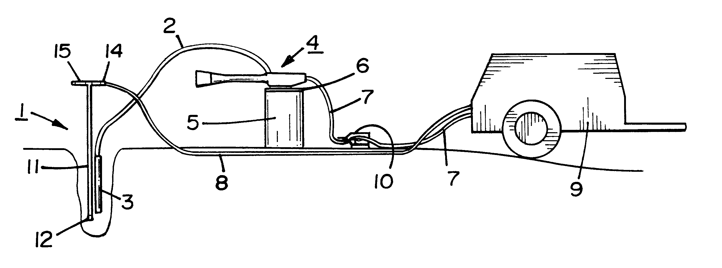
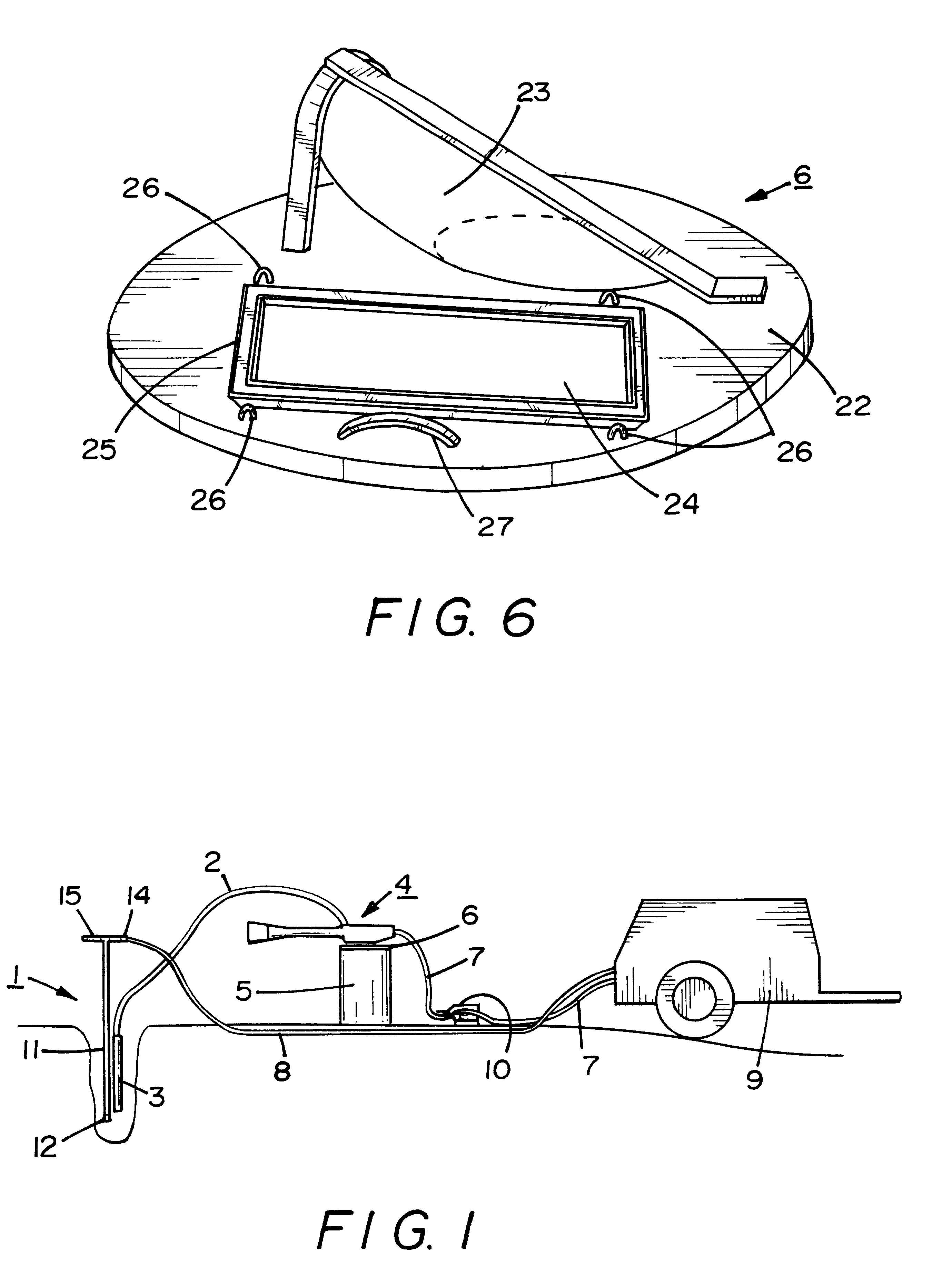
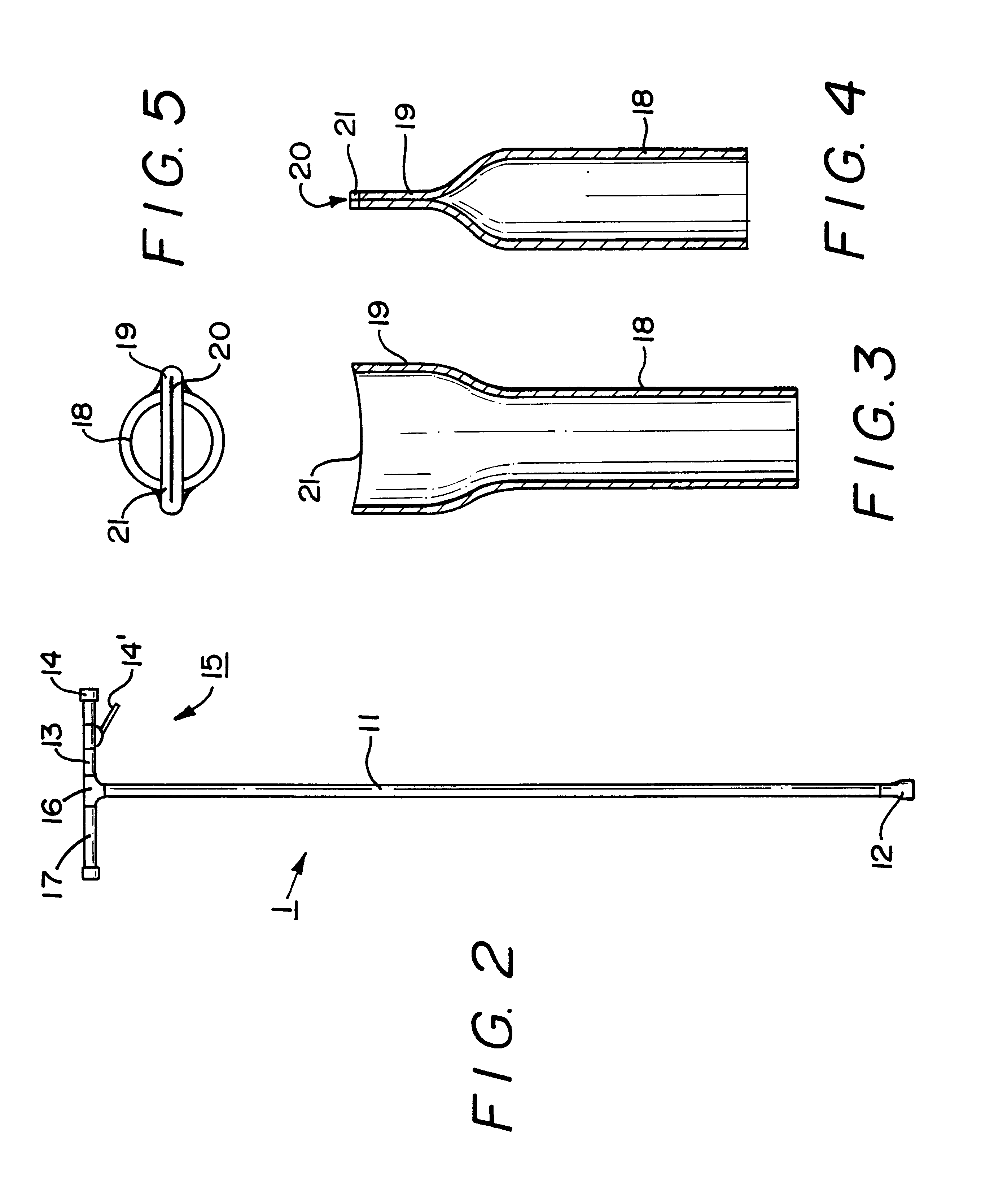
[0037]As shown in FIG. 1, the vacuum excavation system of the invention includes an air lance 1 arranged to direct air at supersonic speeds at a material to be excavated, and a material pickup hose 2 arranged to remove the loosened dirt from the excavation. The material pick-up hose 2 can be an ordinary hose, PVC pipe, or combinations of hoses and pipes, preferably having at least a 4″ diameter for soil excavation applications, although hose 2 is illustrated in FIG. 1 as being fitted with a PVC extension pipe or wand 3, pipe 3 being replaceable with longer or shorter extension pipes depending on the depth of the excavation.

[0038]The pickup hose is connected to a vacuum engine 4, described in greater detail below, which in turn is attached to an airtight material collection drum 5 via a drum head adapter 6, also described in more detail below. The air supply for the vacuum engine and the air supply for the air lance are both supplied by ¾″ standard compressed air hoses 7 and 8 from a...


PUM


Abstract

A vacuum excavation system which incorporates a low consumption air lance, a highly efficient multi-stage vacuum generation system effectively isolated from the waste stream and the air source, and a highly portable material collection system. The air lance includes a cylindrical main body which narrows to a flat taper nozzle at the digging end, and a tee-shaped handle with a swivel type air fitting at one end, while the vacuum generation system is a multi-stage ejector fitted onto a collection drum and consisting of successive venturi tubes with pressure equalizing check valves on the second and higher stages, the material collection system consisting of the drum and hoses or pipes connected to the drum through a separate opening. The system can be powered entirely by one 185 cfm portable air compressor, available from local tool rental firms if one is not owned, so than nearly any contractor, utility company, or design firm can easily outfit themselves for vacuum excavation, at a cost for the excavation system less the air compressor of less than one tenth that of a conventional system.

Description

BACKGROUND OF THE INVENTION[0001]1. Field of the Invention[0002]This invention relates to excavation apparatus of the type which employs high velocity air to loosen soil and a pneumatic vacuum to remove the loosened soil, and in particular to excavation apparatus having an improved air lance nozzle with a blade-shaped orifice, an improved air lance adapted to be rotated during excavation, and an improved pneumatic vacuum system including a multistage venturi ejector adapted to be fitted on a material collection container.[0003]2. Discussion of Related Art[0004]The concept of vacuum excavation has been discussed in a number of prior patents. U.S. Pat. Nos. 4,776,781, 4,936,031, 5,140,759, and 5,361,855 all disclose pneumatic soil excavation systems in which a jet of air is directed against a mass of soil by a hand-held nozzle to cause the mass to break up, and in which the loosened soil is collected by entraining it in an air flow carried by a pipe or conduit, and depositing the entr...

Claims


Application Information

Patent Timeline
Patent Type & Authority Patents(United States)
IPC IPC(8): E02F3/88E02F3/92
CPCE02F3/90E02F3/9206
Inventor HAYES, PAUL
Owner UTILISCOPE CORP
Why Eureka
Try Eureka