Image processing method, image processing apparatus and data recording medium

a technology of image processing and data recording media, applied in the direction of code conversion, color television with bandwidth reduction, television systems, etc., can solve the problems of no ac prediction may be carried out, and degrading the efficiency of variable-length coding, etc., to achieve accurate and efficient decoding

Inactive Publication Date: 2006-10-03
PANASONIC INTELLECTUAL PROPERTY CORP OF AMERICA
View PDF24 Cites 11 Cited by
  • Summary
  • Abstract
  • Description
  • Claims
  • Application Information

AI Technical Summary

Benefits of technology

[0055]It is an object of the present invention to provide image processing apparatuses and image processing methods in which, in coding of an interlaced image in which macroblocks having different DCT types coexist, or in coding of a specific progressive image, a scan method that improves the efficiency of variable-length coding can be adaptively selected, thereby realizing highly efficient coding.

Problems solved by technology

In addition, in a case where the efficiency of variable-length coding is degraded by predicting AC coefficients, no AC prediction may be carried out.
However, in interlaced image coding in which frame DCT blocks and field DCT blocks coexist, since a field DCT block and a frame DCT block have different distributions of DCT coefficients, coefficients of about the same size are not consecutive when the same scan changing method is used, so that the efficiency of variable-length coding is degraded.
Further, also in inter-frame predictive coding of an interlaced image in any of the conventional image processing apparatuses, the above-mentioned problem arises because macroblocks having different DCT types coexist.

Method used


Image

  • Image processing method, image processing apparatus and data recording medium
  • Image processing method, image processing apparatus and data recording medium
  • Image processing method, image processing apparatus and data recording medium

Examples


embodiment 1

[Embodiment 1]

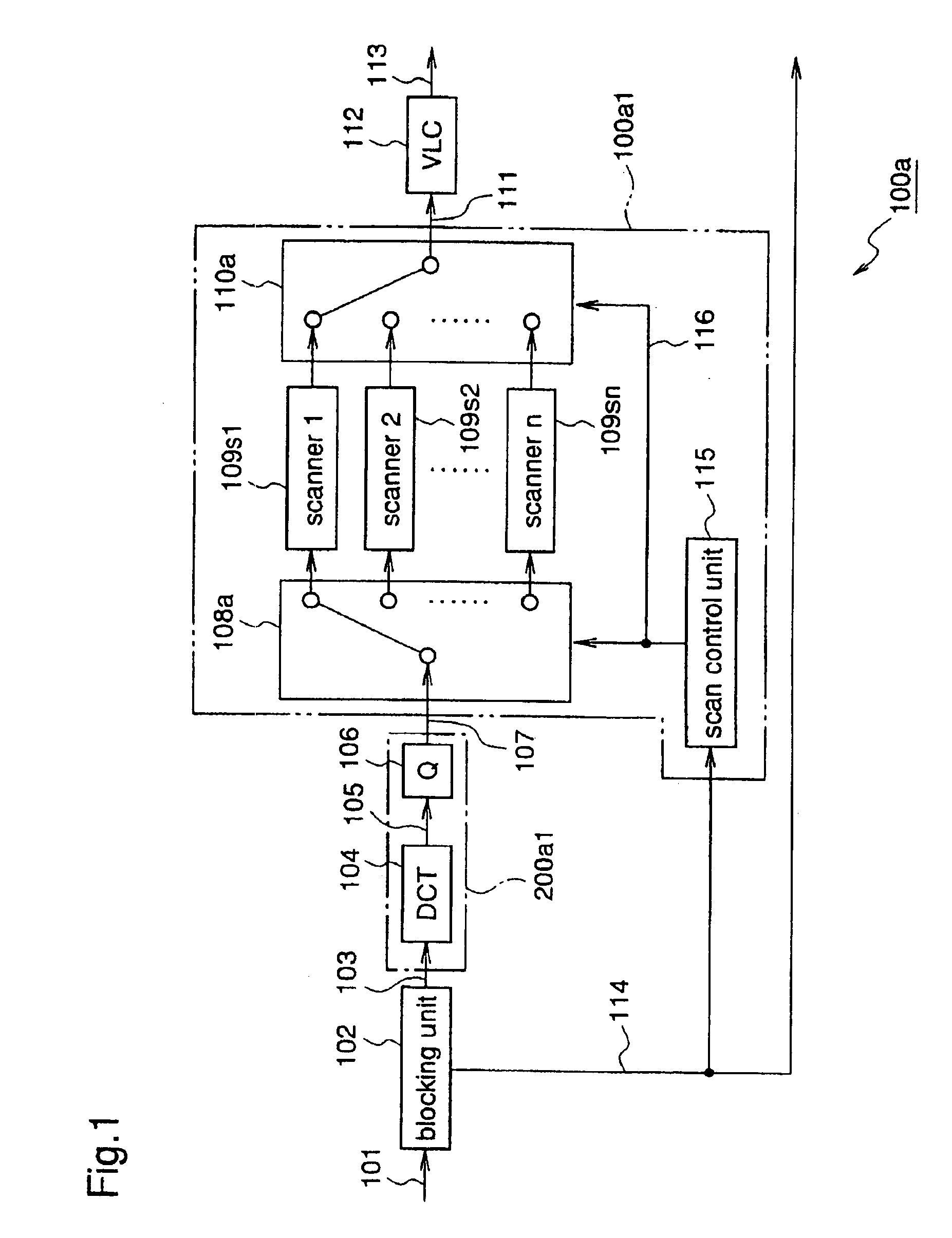
[0163]FIG. 1 is a block diagram illustrating a construction of an image processing apparatus according to a first embodiment of the present invention. In FIG. 1, reference numeral 100a designates the image processing apparatus (image coding apparatus) according to the first embodiment of the invention. This image coding apparatus 100a includes the construction. of the conventional image coding apparatus 200a shown in FIG. 26, and a circuit construction for performing adaptive scan changing processing in which a scan method is changed according to a DCT (discrete cosine transformation) type of a coding target block. Herein, the DCT type represents a signal indicating whether the coding target block has been subjected to frame DCT processing or field DCT processing.

[0164]That is, the image coding apparatus 100a according to the first embodiment of the invention has a scanning unit 100a1 for performing the above-mentioned adaptive scan changing processing, in place of the...

embodiment 2

[Embodiment 2]

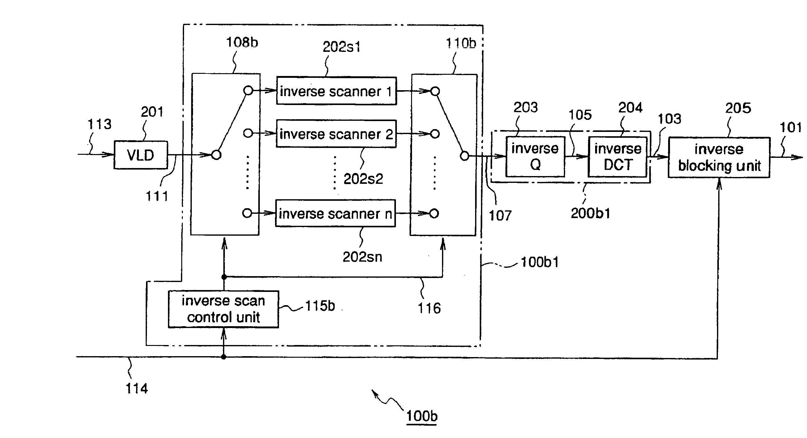
[0193]FIG. 6 is a block diagram illustrating a construction of an image processing apparatus according to a second embodiment of the present invention. In FIG. 6, reference numeral 100b designates the image processing apparatus (image decoding apparatus) according to the second embodiment of the invention. This image decoding apparatus 100b includes the construction of the conventional image decoding apparatus 200b shown in FIG. 28, and a circuit construction for performing adaptive inverse scan changing processing in which an inverse scan method is changed according to a DCT type of a decoding target block. Herein, the DCT type represents a signal indicating whether a coded block corresponding to the decoding target block has been subjected to frame DCT processing or field DCT processing.

[0194]That is, the image decoding apparatus 100b according to the second embodiment of the invention has an inverse scanning unit 100b1 for performing the above-mentioned adaptive inv...

embodiment 3

[Embodiment 3]

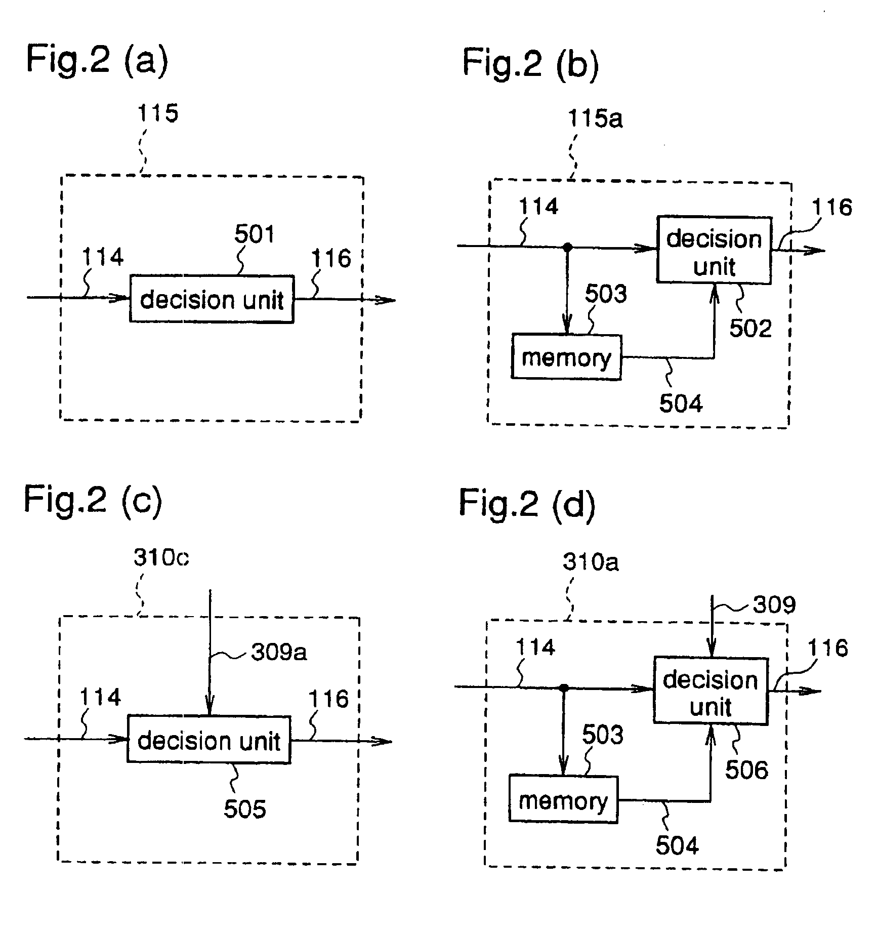
[0208]FIG. 8 is a block diagram illustrating a construction of an image processing apparatus according to a third embodiment of the present invention. In FIG. 8, reference numeral 100c designates the image processing apparatus (image coding apparatus) according to the third embodiment of the invention. This image coding apparatus 100c has a scan control unit 310c for generating a control signal 116 on the basis of both first prediction information (a first parameter concerning intra-frame prediction) 309a and DCT type information 114 of a coding target block, in place of the scan control unit 1401c in the conventional image coding apparatus 200c shown in FIG. 29.

[0209]Herein, as in the conventional image coding apparatus 200c, the first parameter 309a concerning intra-frame prediction includes ON / OFF information and prediction direction information of AC prediction, and second prediction information (a second parameter) 309b includes only ON / OFF information of AC predi...


PUM


Abstract

An image processing method for dividing a digital image signal into plural image signals corresponding to plural blocks constituting a single display screen, and performing block-by-block coding of the image signals of the respective blocks, comprises transforming an image signal of a coding target block to be subjected to coding into frequency components by frame-by-frame frequency transformation on a frame basis or field-by-field frequency transformation on a field basis; setting a processing order for coding the frequency components corresponding to the image signal of the coding target block, according as the image signal of the coding target block has been subjected to the frame-by-frame frequency transformation or the field-by-field frequency transformation; and successively coding the frequency components corresponding to the image signal of the coding target block according to the order which has been set. Therefore, in coding of an interlaced image or a specific progressive image in which frame DCT blocks and field DCT blocks coexist, a run length is increased, thereby improving coding efficiency.

Description

FIELD OF THE INVENTION[0001]The present invention relates to image processing methods, image processing apparatuses, and data recording media and, more particularly, to image processing methods, image processing apparatuses, and data recording media in which, in variable-length coding of frequency components of an interlaced image signal, a sequence of the frequency components is adaptively rearranged, thereby improving coding efficiency.BACKGROUND OF THE INVENTION[0002]In recent years, discrete cosine transformation (DCT) has been widely utilized in image coding processing. In MPEG as a representative image coding method, an input image signal is divided correspondingly to plural rectangular blocks constituting a single display screen as units of DCT processing, and DCT processing is performed block by block to the blocked image signal.[0003]A specific description is given of image coding in MPEG.[0004]FIG. 26 is a block diagram illustrating a construction of a conventional image p...

Claims


Application Information

Patent Timeline
Patent Type & Authority Patents(United States)
IPC IPC(8): H04B1/66H04N19/60H03M7/36H04N19/129H04N19/134H04N19/172H04N19/176H04N19/423H04N19/503H04N19/61H04N19/625H04N19/91
CPCH04N19/105H04N19/176H04N19/129H04N19/60H04N19/593H04N19/16H04N19/18H04N19/48H04N19/625
Inventor NISHI, TAKAHIROTAKAHASHI, TOSHIYABOON, CHOONG SENGKADONO, SHINYA
Owner PANASONIC INTELLECTUAL PROPERTY CORP OF AMERICA
Why Eureka
Try Eureka