Apparatus and methods for cooling slot step elimination

a technology of apparatus and cooling slot, which is applied in the field of apparatus and methods for reducing stress on turbine blades, can solve the problems of large stress concentration with high terminal stress, easy potential early fatigue and blade failure of trailing edge axial cracks, so as to improve the longevity and performance of the turbine blade, reduce the stress concentration, and reduce the fatigue of the airfoil

Inactive Publication Date: 2006-11-14
GENERAL ELECTRIC CO
View PDF5 Cites 8 Cited by
  • Summary
  • Abstract
  • Description
  • Claims
  • Application Information

AI Technical Summary

Benefits of technology

[0008]More specifically, the die includes a tab positioned such that a continuous and smooth contour is formed from the first trailing edge slot recessed wall to a juncture of the airfoil and the platform at the filled. Once the tab is cast onto the airfoil core die, the first step, which is typically located near the juncture of the airfoil and an airfoil platform, is partially eliminated. The elimination of at least a portion of the step reduces stress conc

Problems solved by technology

The airfoil trailing edge region is exposed to such high temperature gases and is prone to failure due to difficulties associated with providing adequate cooling to the region.
The step in the slot located closest to the platform may cause a large stress concentration with high terminal stresses present.
The high ther

Method used


Image

  • Apparatus and methods for cooling slot step elimination
  • Apparatus and methods for cooling slot step elimination
  • Apparatus and methods for cooling slot step elimination

Examples


Embodiment Construction

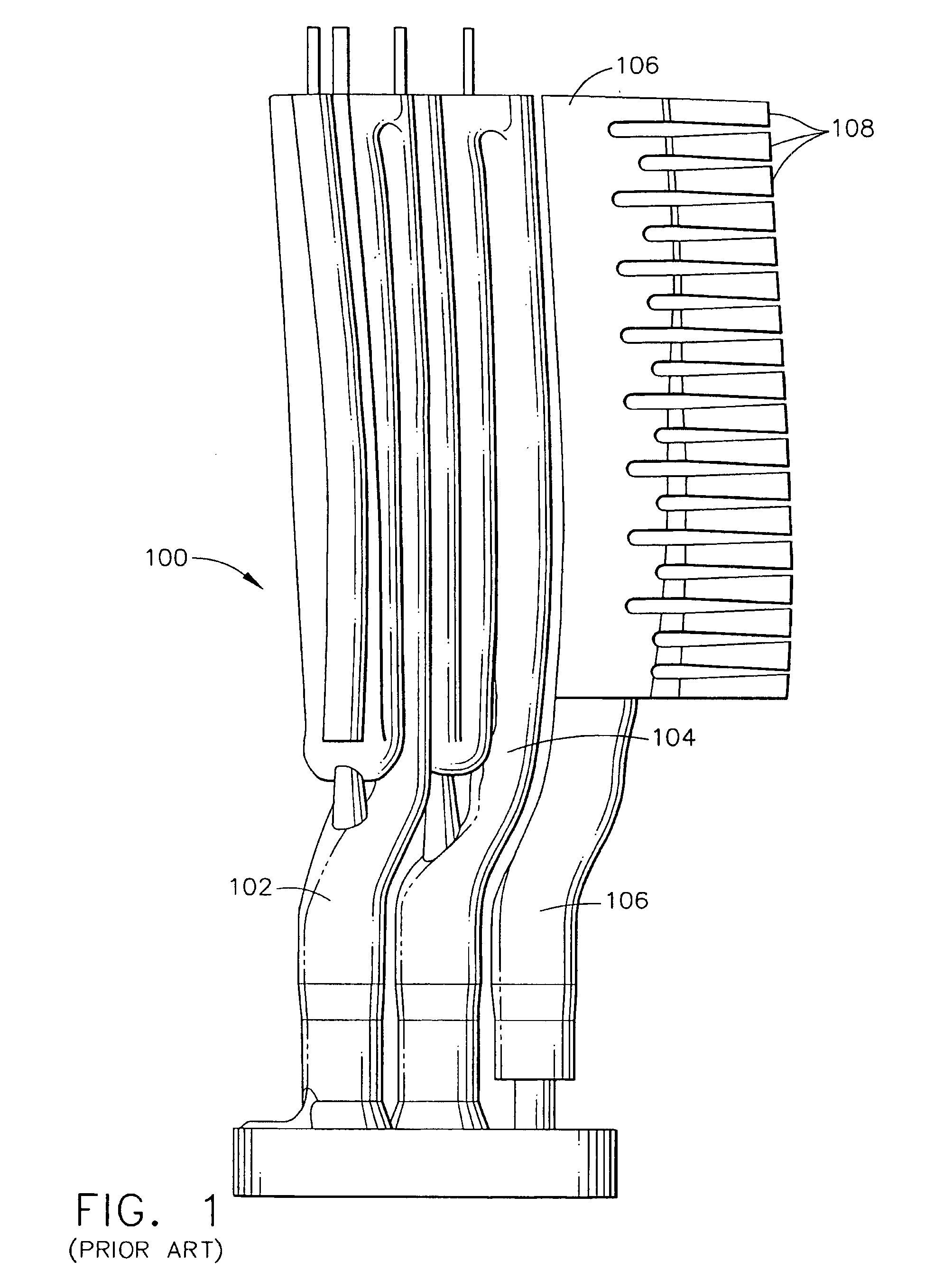
[0015]FIG. 1 illustrates a known airfoil coil 100 utilized for fabricating turbine blades (not shown). Airfoil core 100 includes a first serpentine cooling channel 102, a second serpentine cooling channel 104, an aft wedge channel 106, and a plurality of fingers 108 extending from aft wedge channel 106.

[0016]Airfoil core 100 is fabricated by injecting a liquid ceramic and graphite slurry into core die (not shown). The slurry is heated to form a solid ceramic airfoil core 100. The airfoil core is suspended in an airfoil die (not shown) and hot wax is injected into the airfoil die to surround the ceramic airfoil core. The hot wax solidifies and forms an airfoil (not shown in FIG. 1) with the ceramic core suspended in the airfoil.

[0017]The wax airfoil with the ceramic core is then coated with multiple layers of ceramic and heated to remove the wax, thus forming a cavity shell having the shape of the airfoil. The shell is the cured in a heated furnace. Molten metal is then poured into t...


PUM

PropertyMeasurementUnit
Distanceaaaaaaaaaa

Abstract

An airfoil core die includes a tab for forming a continuous and smooth contour and extension of a first trailing edge slot recessed all to a bottom of the airfoil. The contour is formed on each airfoil core at injection and is maintained through to finish casting of the airfoil.

Description

BACKGROUND OF THE INVENTION[0001]This invention relates generally to turbine engines and, more particularly, to apparatus and methods for reducing stress on turbine blades.[0002]Turbine blades include an airfoil, a platform, and a shank. The airfoil has a leading edge and a trailing edge, with the trailing edge being relatively thin in comparison to the leading edge. Typically turbine blades are subjected to high temperature gases by a combustor located upstream from the turbine blades. The airfoil trailing edge region is exposed to such high temperature gases and is prone to failure due to difficulties associated with providing adequate cooling to the region.[0003]To facilitate preventing airfoil failure, a plurality of slots are located in the airfoil trailing edge and cool air is discharged from the slots to cool the trailing edge. These slots sometimes are referred to herein as trailing edge slots.[0004]Turbine engine airfoils are cast with land areas, or ribs, located between t...

Claims


Application Information

Patent Timeline
IPC IPC(8): F01D5/18B23P15/02
CPCB22C9/103B23P15/02F01D5/186F01D5/187F05D2230/21
Inventor DANOWSKI, MICHAEL J.BRAINCH, GULCHARAN S.CLARKE, JONATHAN PHILLIP
Owner GENERAL ELECTRIC CO
Why Eureka
Try Eureka