
Boosted air source heat pump

a heat pump and air source technology, applied in the field of air source heat pumps, can solve the problems that the potential of the power source heat pump is significant, and achieve the effect of sufficient and efficient heating and increased refrigerant pumping capacity

Inactive Publication Date: 2007-05-15
NORTHEAST BANK
View PDF47 Cites 11 Cited by
  • Summary
  • Abstract
  • Description
  • Claims
  • Application Information

AI Technical Summary

Benefits of technology

"The present invention is a system and method for a heat pump that can efficiently heat a wide range of outdoor temperatures. It uses a flexible refrigeration circuit and a novel oil equalization method between the primary and booster compressors. The system includes a multi-cylinder unloadable compressor and a bleed line for subcooling the refrigerant. The invention achieves a high level of efficiency in heating, with a Carnot efficiency level of at least 26% at an outdoor temperature of 0°F. The invention also allows for a smaller amount of energy to be used compared to traditional systems, making it more suitable for cold climates."

Problems solved by technology

Fundamental Carnot Theory thermodynamic principles unquestionably show that electric powered air source heat pumps indeed to have significant potential in cold climates.

Method used


Image

  • Boosted air source heat pump
  • Boosted air source heat pump
  • Boosted air source heat pump

Examples


example 1

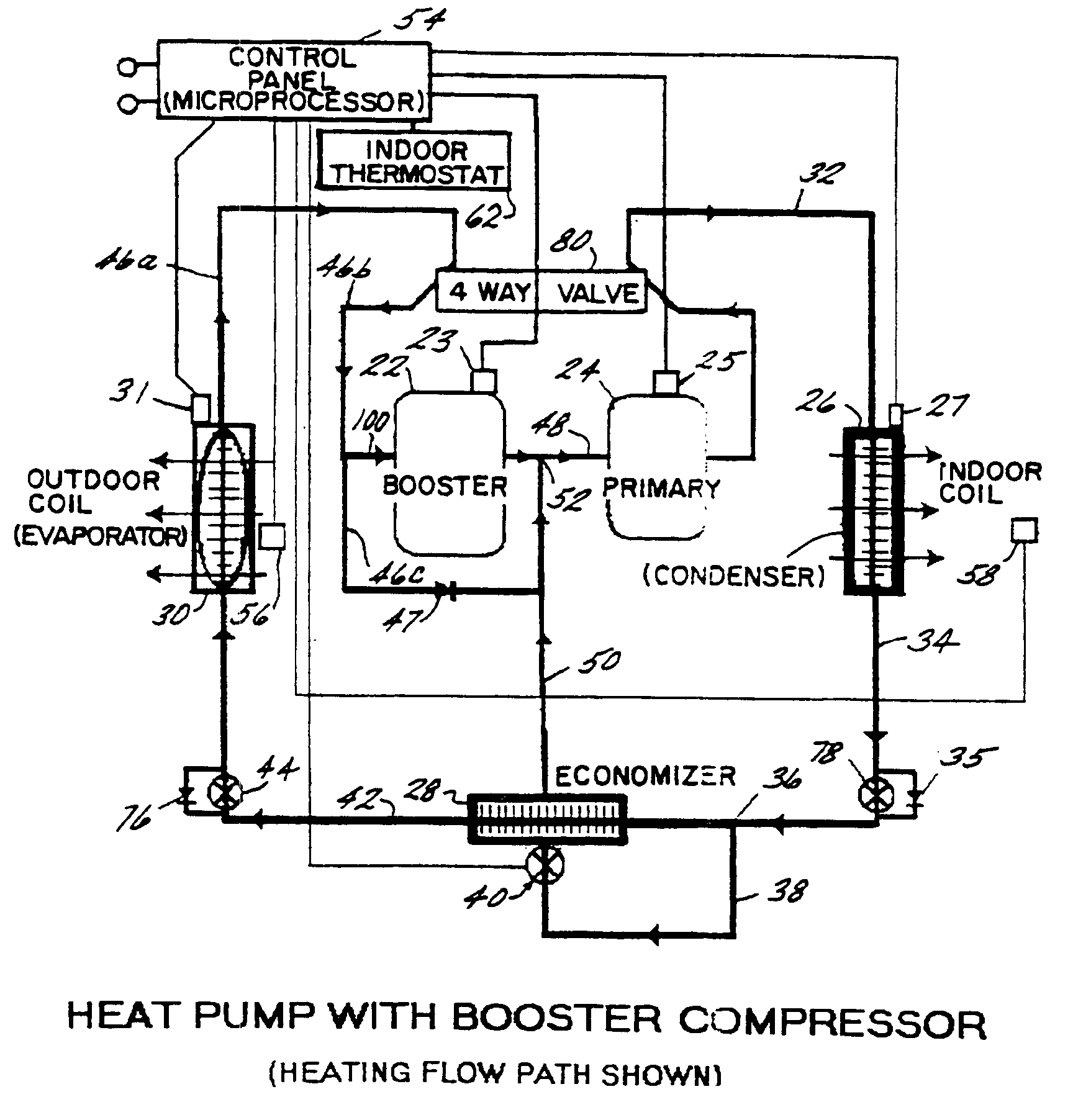
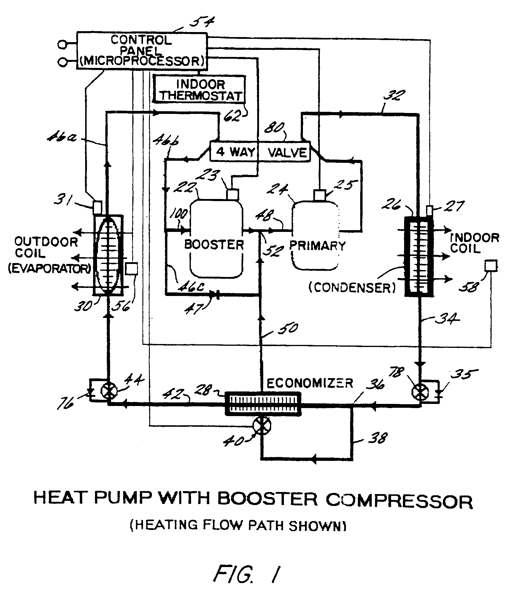
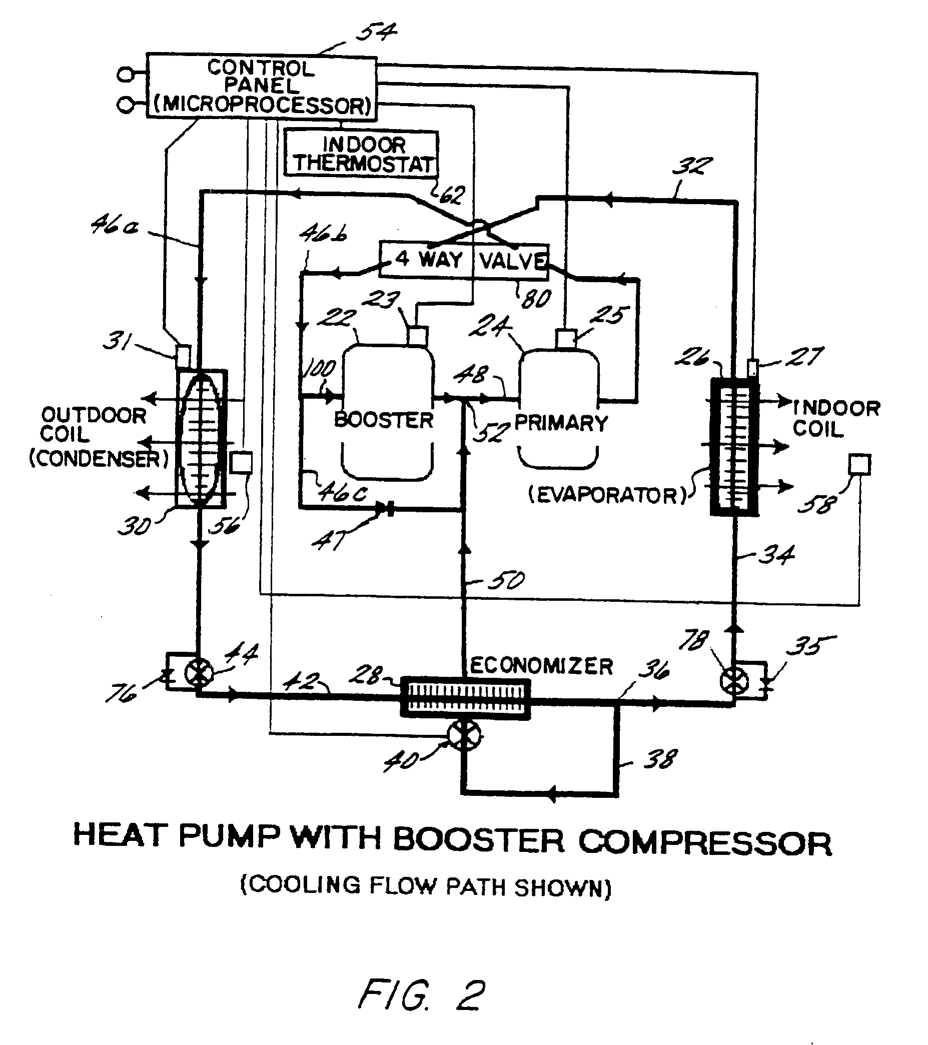
[0060]Referring now to FIGS. 6 and 7, a heating capacity chart and an exemplary operating sequence are shown. It will be recalled that thermostat 62 preferably has three stages in the heat mode. The thermostat stages signal microprocessor 54, which, in turn, sends signals to allow (i.e., control) the operation of the compressors, and / or one or both cylinders of the compressors, and / or the economizer.

[0061]Typically, the heating cycle starts when the first stage or step of indoor thermostat 62 calls for heat. When this occurs somewhere between 75° F. and above 50° F. outdoor ambient temperature, as sensed by sensor 56, one piston of primary compressor 24 is allowed to operate, i.e., is activated by a signal from microprocessor 54. Depending on the configuration, this provides 40% or 50% of the displacement of primary compressor 24. This mode of operation is identified in FIGS. 6 and 7 as 010, signifying 0 cylinder operation of the booster, 1 cylinder operation of the primary and no o...

example 2

[0068]While incorporation of economizer 28 in the system is preferred, the economizer can be omitted. In that case, the displacement ratio of the booster compressor 22 to primary compressor 24 would be increased sufficiently to realize a system capacity about that of the system with the economizer, understanding that a system efficiency loss would occur due to the absence of the economizer. In this case, at conditions of 0° F. outdoor ambient and 70° F. indoor heated space temperature, the heating coefficient of performance (C.O.P.) will be at least 1.5 and may approach 2. By way of example, the displacement ratio of booster compressor 22 to primary compressor 24 could be increased to about 1.4:1 to about 1.7:1. Referring to FIGS. 6 and 7, with the economizer eliminated, the 211 line would be eliminated, and the 211 line is replaced by a 220 line, with the allowance point being the outdoor ambient temperature at which the 221 line was previously allowed, i.e., between about 15° F.-2...


PUM


Abstract

A boosted source heat pump (BSHP) is presented having a primary compressor, a booster compressor, an economizer, and a lubricant management system. At least the primary compressor is a twin-single compressor. The lubricant management system includes traps to prevent migration of lubricant to a non-operating compressor, and aspiration tubes from the sump to the low pressure intake zone to each compressor.

Description

BACKGROUND AND CROSS REFERENCE[0001]This invention relates to air-source heat pumps. More particularly, it relates to new and improved air source heat pumps especially suitable for use in normally colder climates. This invention is an improvement on my U.S. Pat. No. 5,927,088, the entire contents of which are incorporated herein by reference.[0002]The following discussion of typical prior art heat pumps refers to air-source heat pumps other than the heat pumps disclosed in my U.S. Pat. No. 5,927,088.[0003]The air-source heat pump system is the most prevalent type of heat pump used in the world today. This is the case whether one is discussing room units, residential central type, ductless splits, or rooftop commercial systems.[0004]Although the air-source concept in general has a high application potential worldwide, its popularity in the United States and elsewhere has been greatest in mild climate areas. This is because the compressor-derived heating capacity of typical prior art ...

Claims


Application Information

Patent Timeline
Patent Type & Authority Patents(United States)
IPC IPC(8): F25B13/00F04B9/04F04B39/00F25B1/10F25B31/00F25B49/02
CPCF04B9/04F04B39/0094F25B1/10F25B13/00F25B31/002F25B49/02F25B2400/13
Inventor SHAW, DAVID N.
Owner NORTHEAST BANK
Learn More