
Method and apparatus for inspecting pipelines from an in-line inspection vehicle using magnetostrictive probes

a magnetostrictive probe and pipeline technology, applied in the direction of instruments, diagnostic recording/measure, specific gravity measurement, etc., can solve the problems of heavy weight, difficult to handle, and limited internal access to the pipe wall that cannot be interrupted,

Inactive Publication Date: 2008-09-23
SOUTHWEST RES INST
View PDF16 Cites 9 Cited by
  • Summary
  • Abstract
  • Description
  • Claims
  • Application Information

AI Technical Summary

Benefits of technology

[0028]It is a further object of the present invention to provide magnetostrictive sensor devices appropriate for use in conjunction with the inspection of pipeline structures that progressively inspect the circumference of the pipeline structure for anomalies, corrosion, fractures, and the like in a cost effective manner.

Problems solved by technology

These efforts in the past have focused primarily on the external inspection of piping, tubing and steel strands / cables wherein the nature of the structure is such that uninterrupted internal access to the pipe wall is very limited.
Magnetic flux leakage devices work well, although they are heavy and difficult to handle.
In most instances, MFL devices lack the flexibility to accommodate different pipe diameters, and as such different devices are needed for each pipeline diameter to be inspected.
Such ultrasonic devices work reasonably well but tend to be very expensive to build and operate.
Because of the high inspection costs associated with ultrasonic devices, the gas pipeline industry has devoted much research to finding a more economical approach to pipeline inspection.

Method used


Image

  • Method and apparatus for inspecting pipelines from an in-line inspection vehicle using magnetostrictive probes
  • Method and apparatus for inspecting pipelines from an in-line inspection vehicle using magnetostrictive probes
  • Method and apparatus for inspecting pipelines from an in-line inspection vehicle using magnetostrictive probes

Examples


Embodiment Construction

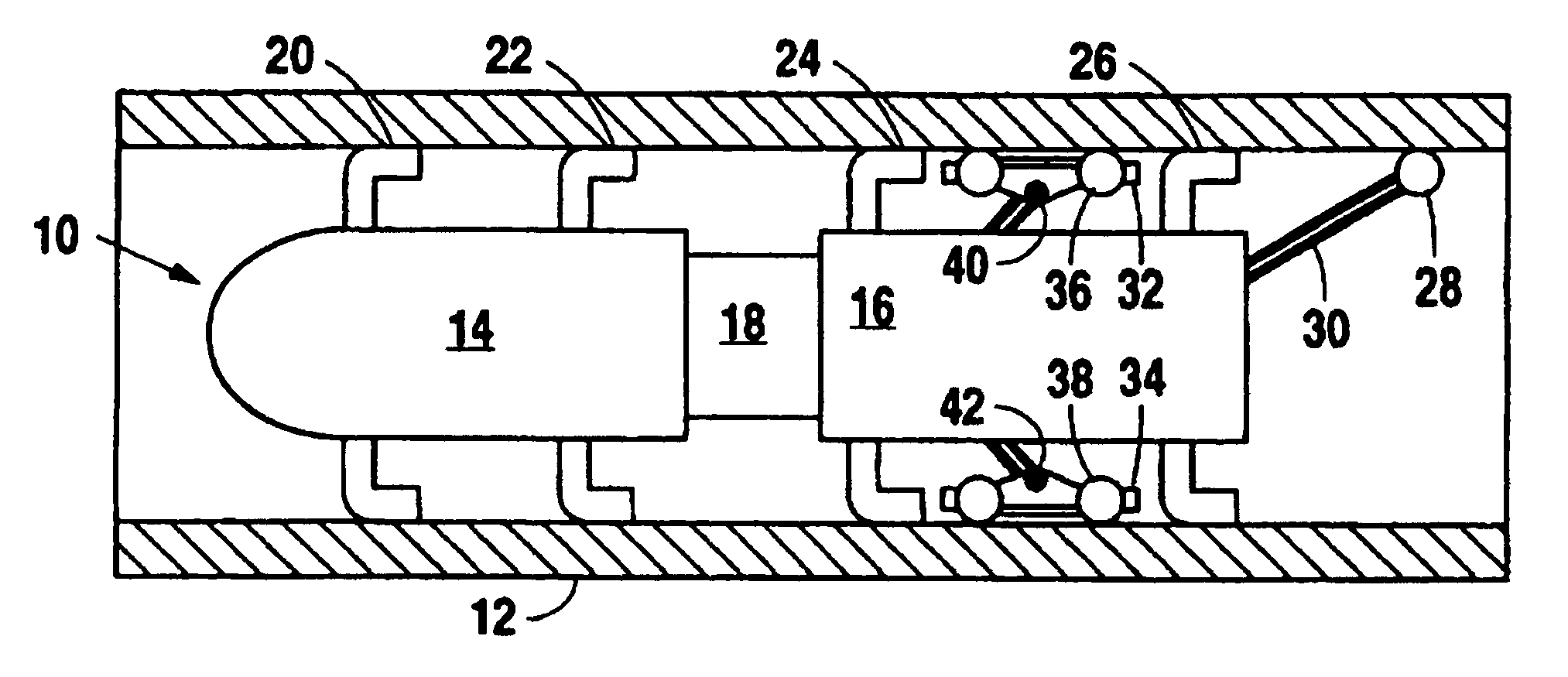
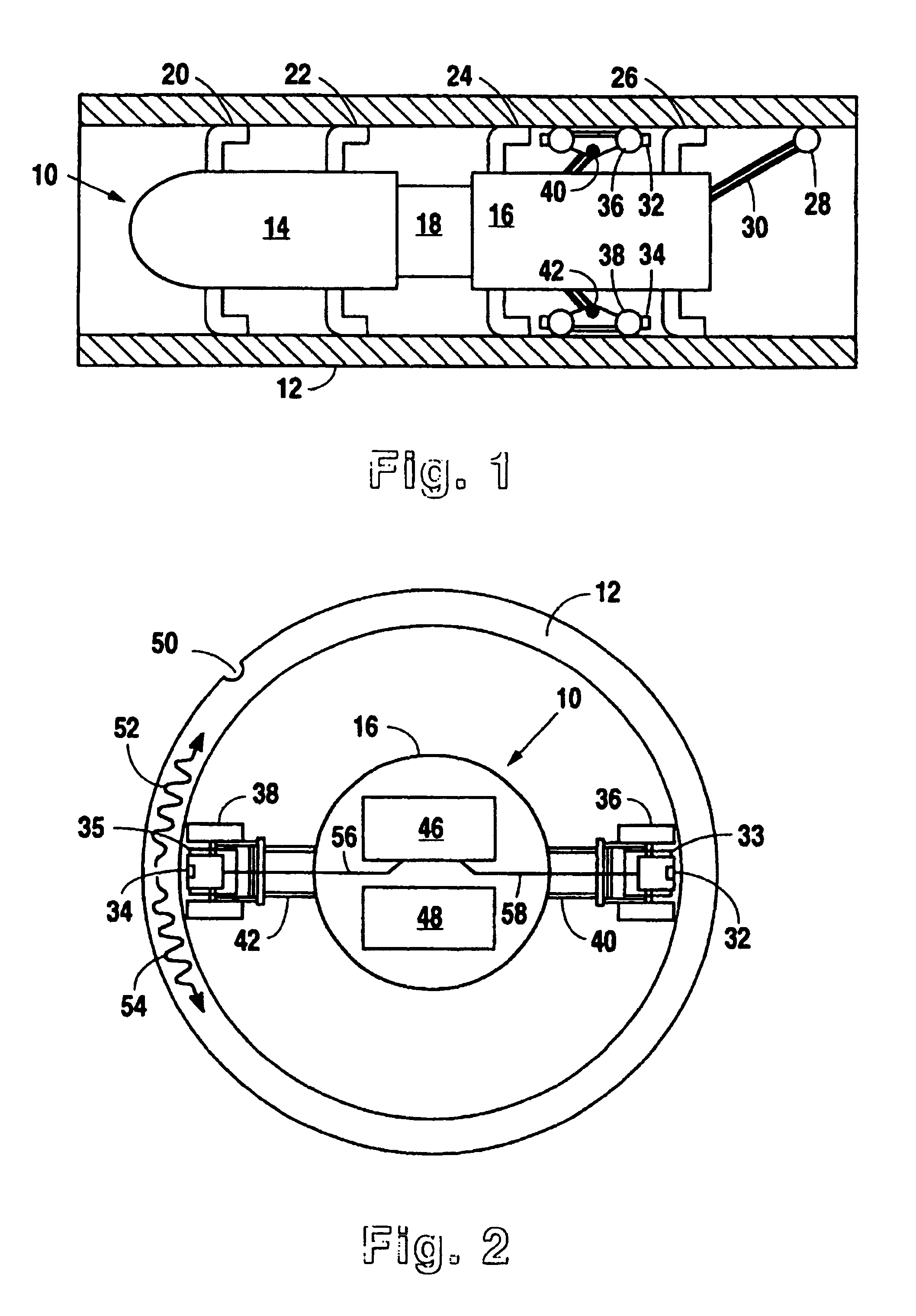
[0039]Reference is made first to FIG. 1 for a description of the structure of a preferred embodiment of the present invention shown in longitudinal cross section and positioned within a typical gas pipeline. In FIG. 1, pipeline wall 12 may be any of a number of standard sized gas pipelines, an example of which might be a 24 inch outside diameter, 0.562 inch thick pipe wall. In-line inspection vehicle 10 is comprised primarily of battery section 14 and sensor / instrument section 16. Sections 14 and 16 are connected together by a flexible coupling 18 which provides the necessary power connections between the sections and permits movement of in-line inspection vehicle 10 through bends and curves in pipeline 12.

[0040]In-line inspection vehicle 10 is propelled down the length of pipeline 12 by the pressurized gas carried through the pipeline. This propulsion is accomplished by use of a number of flexible cups 20, 22, 24 and 26 that are positioned in spaced arrangement on battery section 1...


PUM

PropertyMeasurementUnit
distancesaaaaaaaaaa
lengthaaaaaaaaaa
frequencyaaaaaaaaaa

Abstract

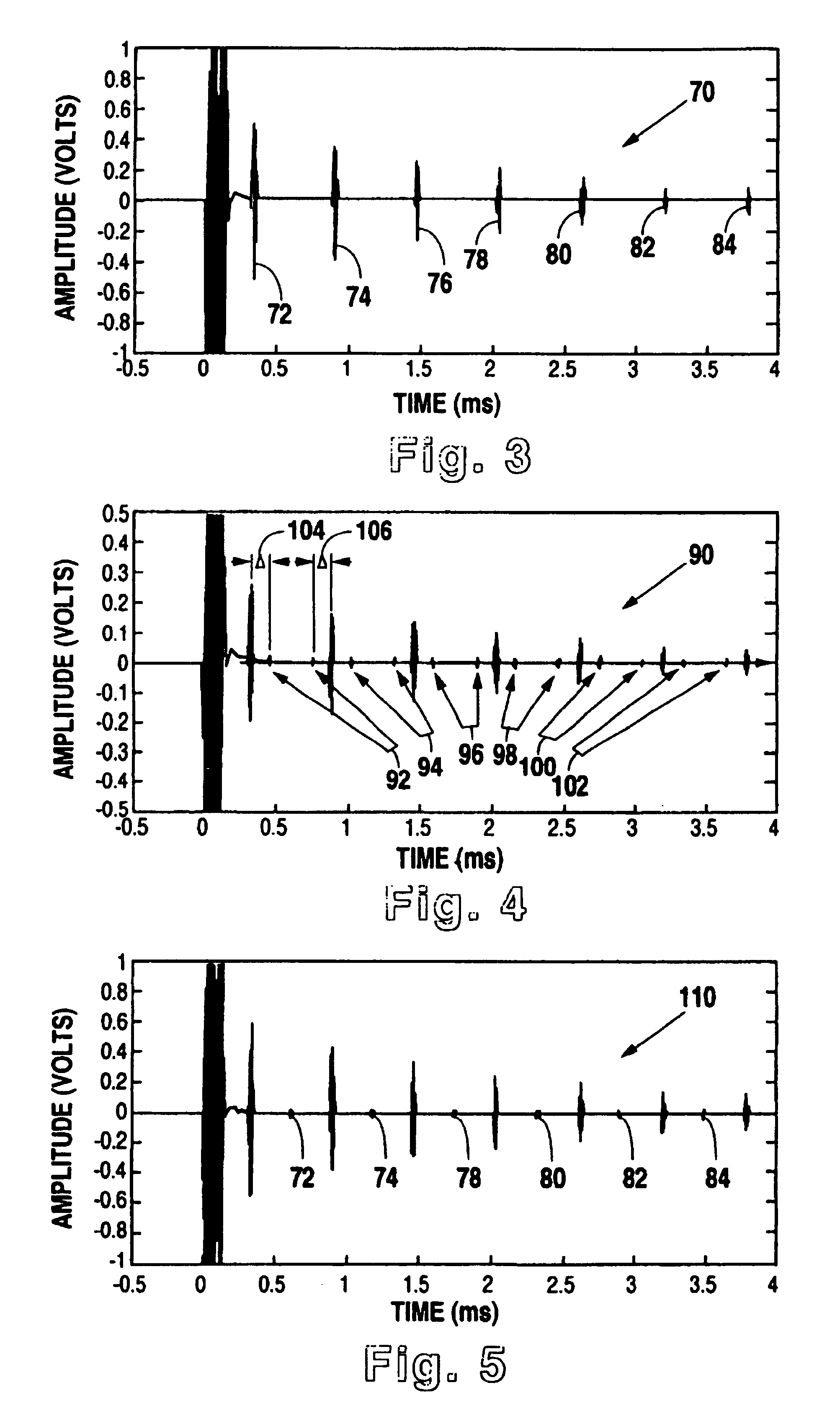
A method and system for implementing magnetostrictive sensor techniques for the nondestructive evaluation of pipeline structures. The system consists of a magnetostrictive sensor instrument unit, a data storage unit, and a plurality of magnetostrictive sensor probes are positioned on an in-line inspection vehicle. The instrumentation unit includes electronics for transmitting excitation pulses to a transmitting magnetostrictive sensor probe as well as electronics for amplifying and conditioning the signals detected by a receiving magnetostrictive sensor probe. The magnetostrictive sensor probes include both plate magnetostrictive sensors and permanent magnets which provide a DC bias magnetic field necessary for magnetostrictive sensor operation. The transmitting and receiving probes are attached to the in-line inspection vehicle by way of mechanical arms on opposing sides of the vehicle. The mechanical arms are spring loaded and are equipped with rollers which maintain the probes at approximately constant distances from the inside diameter of the pipe wall. The method involves generating pulses of shear horizontal waves of frequencies less than 200 kHz. The transmitting magnetostrictive sensor probe generates a wave that propagates in both directions around the circumference of the pipe wall from a point adjacent to the transmitting probe. Both waves are thereafter received at the receiving probe spaced 180 degrees apart from the transmitting probe. Any defect present in the pipe wall within the circumference being investigated will show up in the received signal.

Description

RELATIONSHIP TO OTHER APPLICATIONS[0001]The present application is a continuation-in-part of U.S. patent application Ser. No. 09 / 519,530 filed Feb. 25, 2000, now U.S. Pat. No. 6,294,912, which is the National Phase Entry of PCT patent application Ser. No. PCT / US00 / 06359 filed Feb. 25, 2000, which claims the priority filing of U.S. Provisional Patent Application Ser. No. 60 / 124,763 filed Mar. 17, 1999.BACKGROUND OF THE INVENTION[0002]1. Field of the Invention[0003]The present invention relates generally to methods and devices for the nondestructive evaluation of materials. The present invention relates more specifically to a magnetostrictive sensor based system for the inspection of pipeline structures from an in-line inspection vehicle.[0004]2. Description of the Related Art[0005]The use of magnetostrictive sensors (MsS) in the nondestructive evaluation (NDE) of materials has proven to be very effective in characterizing defects, inclusions, and corrosion within various types of fer...

Claims


Application Information

Patent Timeline
Patent Type & Authority Patents(United States)
IPC IPC(8): G01N27/82G01N29/14G01N29/28G01N33/12G01N22/00G01N29/11G01N29/22G01N29/24G01N29/265
CPCG01N22/00G01N29/11G01N29/22G01N29/2412G01N29/265G01N2291/015G01N2291/0421G01N2291/0422G01N2291/0423G01N2291/044G01N2291/102G01N2291/2623G01N2291/2632G01N2291/2634G01N2291/2636
Inventor KWUN, HEGEONKIM, SANG YOUNG
Owner SOUTHWEST RES INST
Learn More