
Method for adjusting drive roller linefeed distance

Inactive Publication Date: 2009-06-23
HEWLETT PACKARD DEV CO LP
View PDF14 Cites 5 Cited by
  • Summary
  • Abstract
  • Description
  • Claims
  • Application Information

AI Technical Summary

Benefits of technology

[0013]One advantage of the invention is that mean linefeed error for a specific printer is calibrated. Thus, manufacturing tolerances for a given printer model (e.g., roller diameter tolerances) which result in different mean linefeed error for different specimens of such model need not be as tight to achieve desired print quality. Another advantage is that calibration can be achieved using the naked eye without the need for separate, expensive measurement devices. Thus, the calibrations can be performed at home, in the office, or at low cost service centers. Another advantage is that the calibration can be reperformed over the life of the printer. An advantage of having a linefeed adjustment factor which varies as a function of the media type is that better print quality is achieved across a wider range of media types and weights.
[0014]A benefit of this calibration method is that image size is more accurately controlled. Previously, some printers have not allowed the printing region to span the entire page. A border area at the paper margins has been required to allow a distance for over-advances. Because the over-advancing is being reduced, the area allotted for the image can be increased for a given media size. In addition, better control of image size allows for more accurate reproduction of images because distortion from over-advancing and under-advancing is reduced or eliminated. These and other aspects and advantages of the invention will be better understood by reference to the following detailed description taken in conjunction with the accompanying drawings.

Problems solved by technology

A source of mean linefeed error in such a closed loop system is feed roller diameter variation.
In addition, variation in pinch roller force among printers cause different compression of the feed rollers.
For example, the feed roller diameter may wear down over time.
For some print engines this may not introduce a significant change in print quality, but for other high precision print engines even such change in diameter may adversely impact image quality.

Method used


Image

  • Method for adjusting drive roller linefeed distance
  • Method for adjusting drive roller linefeed distance
  • Method for adjusting drive roller linefeed distance

Examples


Embodiment Construction

Host Environment

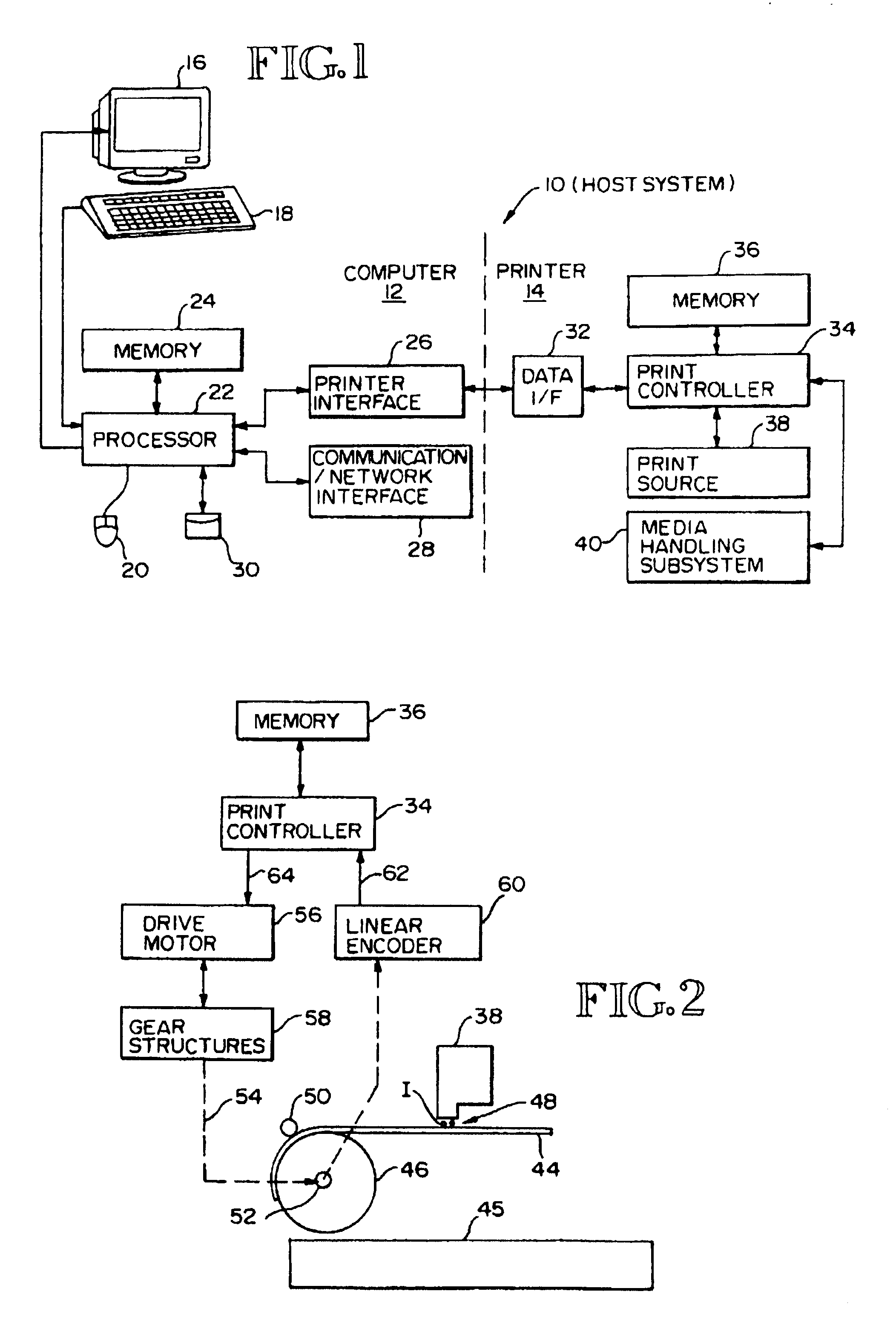
[0021]As used herein the term computer includes any device or machine capable of accepting data, applying prescribed processes to the data, and supplying results of the processes. FIG. 1 shows a host system 10, including a computer system 12 of the kind well known in the art, along with a printer 14. The host system 10 is configured to implement the method and apparatus of this invention. The computer system 12 includes a display monitor 16, a keyboard 18, a pointing / clicking device 20, a processor 22, memory 24, a printer interface 26, a communication or network interface 28 (e.g., modem; ethernet adapter), and a non-volatile storage device 30, such as a hard disk drive, floppy disk drive and / or CD-ROM drive. The memory 24 includes storage area for the storage of application program code, operating system code, and data. The processor 22 is coupled to the display 16, the memory 24, the keyboard 18, the point / clicking device 20, the printer interface 26, the communic...


PUM


Abstract

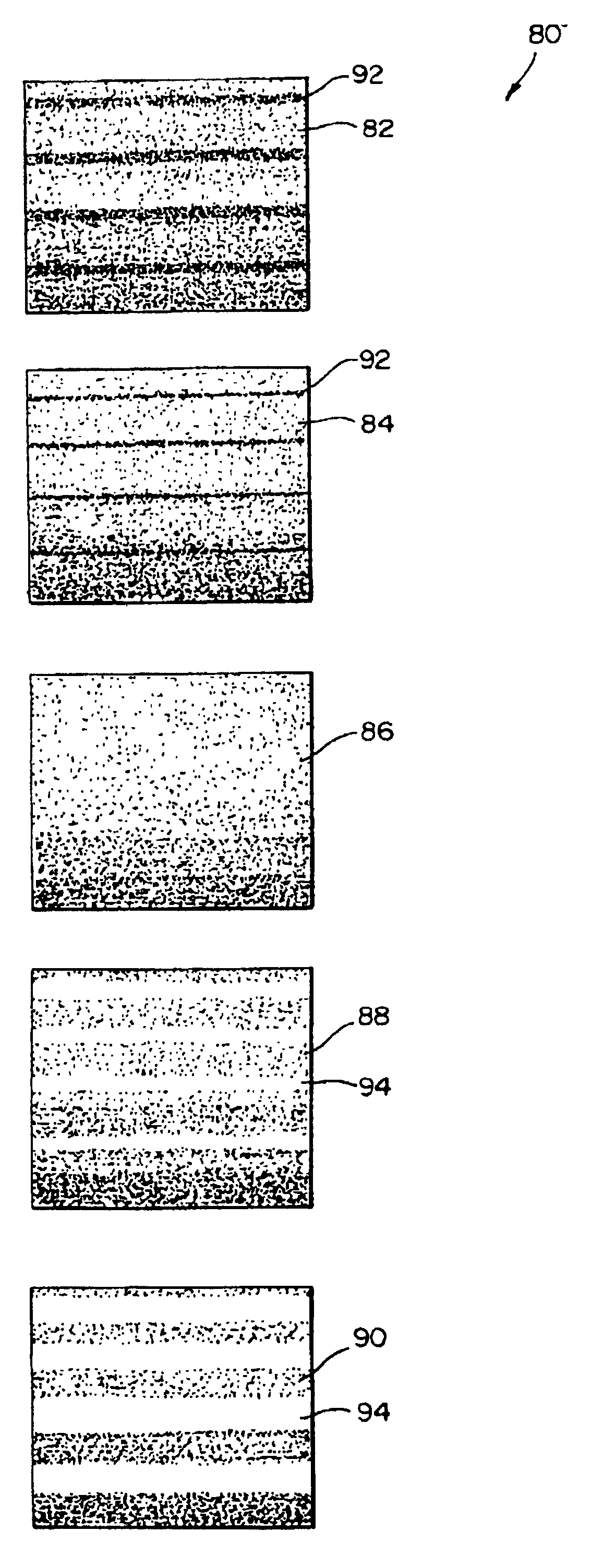
A difference in feed roller diameter from one printer to another causes a media to advance by a different amount for a given rotation of a drive shaft to which the feed roller is coupled. Such variation in advance distance is a linefeed error. Mean linefeed error is determined and corrected by printing a test plot having several areas. Each area is formed of the same image pattern, but is printed at a different linefeed error adjustment to compensate for mean linefeed error. The different adjustments are prescribed and span a typical compensation range for a given print engine model. The different adjustment factors cause banding to occur in some areas. The user picks one of the test pattern areas which has the highest print quality (i.e., least or no banding). The linefeed adjustment factor corresponding to such area is used for normal printing.

Description

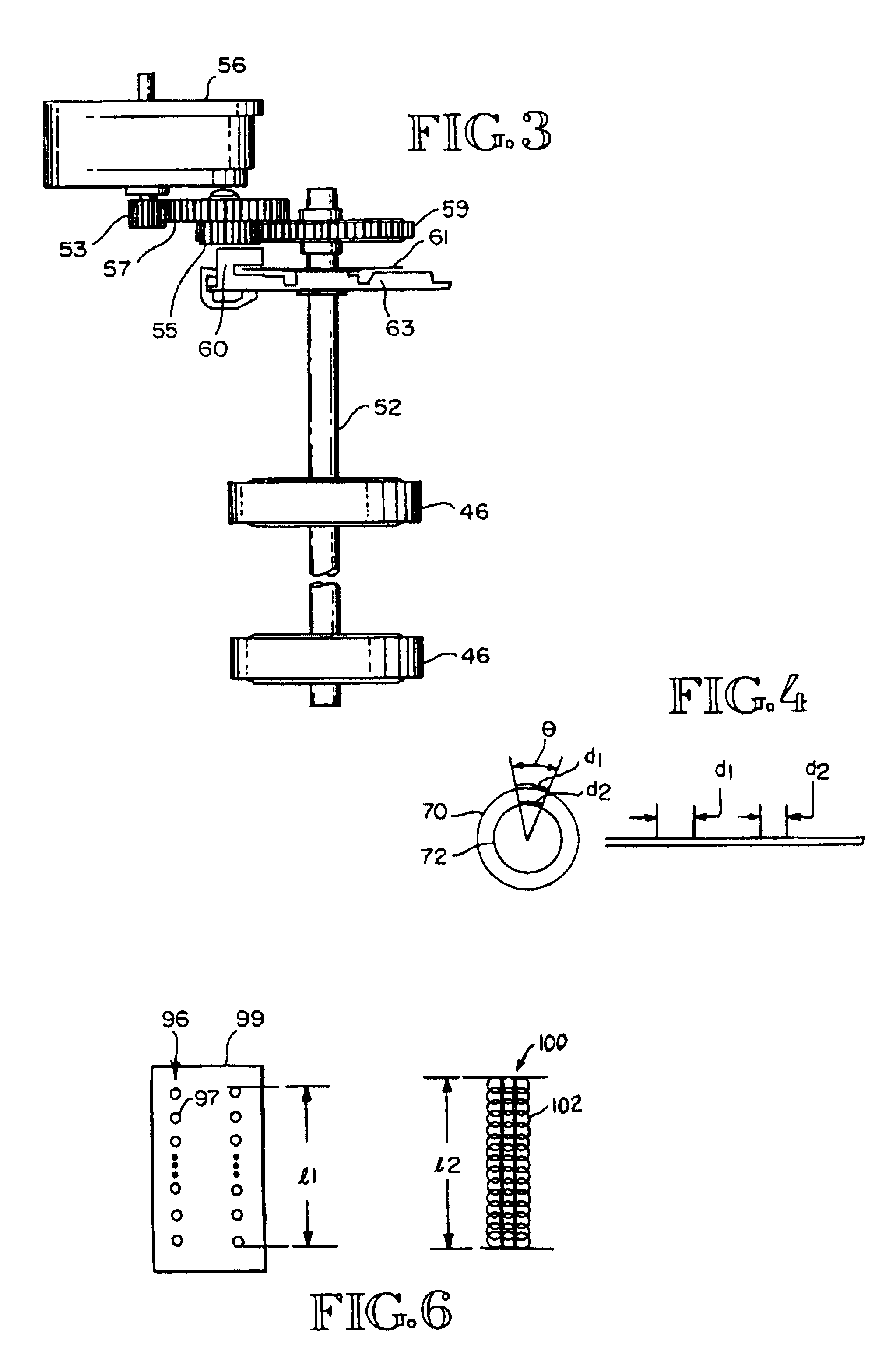
BACKGROUND OF THE INVENTION[0001]This invention relates generally to printing control methods in which a media moves relative to a print source, and more particularly, to a method for controlling a drive shaft of a media roller.[0002]For desktop printers, such as inkjet printers, a media sheet is picked from an input tray and moved along a media path into a print zone where characters, symbols or graphics are printed onto the media sheet. For scanning-type inkjet printers, the media sheet is fed incrementally as a printhead scans across the media sheet. Typically, the media sheet is moved by a linefeed distance between or during printing to a given line.[0003]The media handling system for an inkjet printer includes a set of rollers which move a media sheet along a media path. The rollers are driven by a drive shaft, which in is driven by a drive motor. In many instances there is intermediary gearing for varying the motion of the rollers. A print controller controls the drive motor.[...

Claims


Application Information

Patent Timeline
IPC IPC(8): B41J11/00B41J11/42B41J11/46B41J19/96B41J29/46B65H5/06
CPCB41J11/008B41J11/009B41J11/42B41J11/46
Inventor ARQUILEVICH, DANRASMUSSEN, STEVE O.STEPHENS, VANCE M.
Owner HEWLETT PACKARD DEV CO LP
Learn More