Composite conformable pressure vessel

a pressure vessel and conformation technology, applied in the field of pressure vessels, can solve the problems of reducing the driving range of the vehicle, limiting consumer acceptance of such conversions, and reducing the volume of stored cng, so as to reduce the tendency of adjacent cells to peel apart and strengthen the pressure vessel

Inactive Publication Date: 2010-02-23
NORTHROP GRUMMAN SYST CORP
View PDF42 Cites 27 Cited by
  • Summary
  • Abstract
  • Description
  • Claims
  • Application Information

AI Technical Summary

Benefits of technology

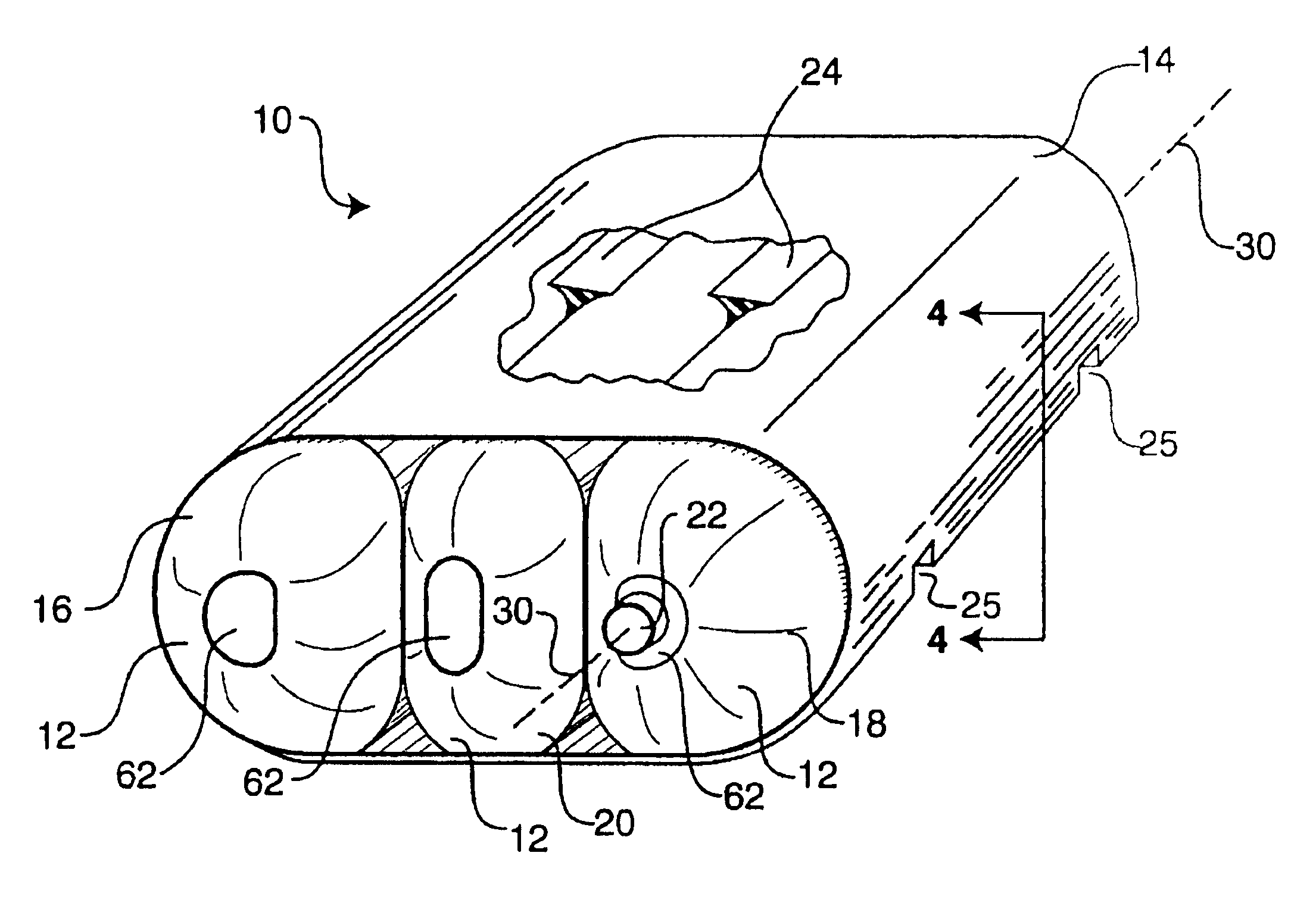
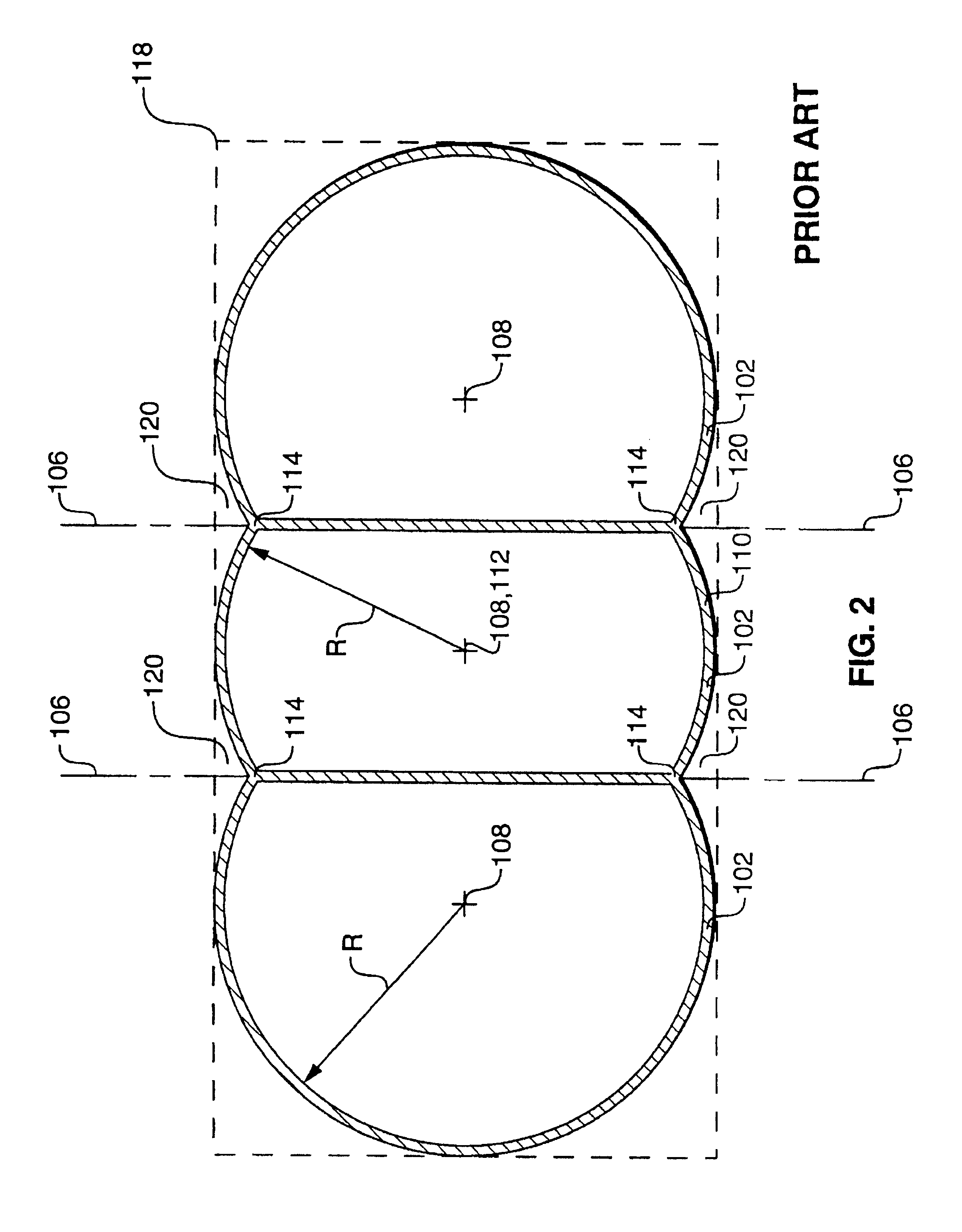
[0022]The radii of the semi-cylindrical interior wall upper and lower portions are the same as the radii of the quartercylindrical upper wall and lower wall, respectively, of the end cells. Thus, the end cells and interior cells of the present pressure vessel are generally tangent to one another where they meet, unlike the lobes of previously known pressure vessels. This aspect of the novel geometry of the present pressure vessel reduces the tendency of adjacent cells to peel apart.
[0023]A web is secured about the end cells and about any interior cells that are present. The web includes a substantially planar upper sheet which is generally tangent to the upper-outer junction of each of the end cells and to the semi-cylindrical upper portion of each interior cell. The web also includes a substantially planar lower sheet which is generally tangent to the lower-outer junction of each of the end cells and to the semi-cylindrical lower portion of each interior cell. The web strengthens the pressure vessel by assisting in holding the cells tangent to one another and by reinforcing the cell walls.
[0024]The pressure vessel of the present invention defines wedge-shaped unused volumes between the web and the cells that are not used for pressurized fluid storage. In one embodiment, the pressure vessel is strengthened by substantially filling the unused volumes with wedges of foam or rubber disposed between the web sheets and the cells.

Problems solved by technology

Unfortunately, the use of conventional CNG cylinders restricts the driving range of the converted vehicle to about 120 to 140 miles, which severely limits consumer acceptance of such conversions.
However, increasing the storage pressure often requires thickening the walls of the storage cylinders to provide them with sufficient structural strength to resist the higher pressure.
Increasing the wall thickness requires either an increase in the external size of the storage cylinders, thereby preventing storage of the cylinders in the space previously occupied by the gasoline tank, or a reduction of the internal storage volume of the cylinders, thereby reducing the volume of stored CNG and hence reducing the vehicle's driving range.
Thickening the walls also increases the weight of the storage cylinders, thereby decreasing the fuel efficiency of the vehicle.
Such tube-and-dome containers have several drawbacks when employed in applications requiring substantially rectangular angular pressure vessels.
The drawbacks of tube-and-dome geometry arise from differences between that geometry and a substantially rectangular geometry.
But building a rectangular shell-shaped CNG vessel sufficiently strong to resist typical CNG storage pressures would require excessively thick walls, because the rectangular shell is so far removed in shape from a sphere.

Method used


Image

  • Composite conformable pressure vessel
  • Composite conformable pressure vessel
  • Composite conformable pressure vessel

Examples


Embodiment Construction

[0041]Reference is now made to the figures wherein like parts are referred to by like numerals. The present invention relates to a pressure vessel generally, and more specifically to a tank for holding compressed natural gas (“CNG”) for fueling a vehicle (not shown). One embodiment of the present pressure vessel is indicated generally at 10 in FIG. 3. This embodiment of the pressure vessel 10 includes three cells 12 secured within a web 14. The three cells 12 include a left end cell 16, a right end cell 18, and one interior cell 20. The cells 12 have a novel geometry and other important characteristics which will be described in detail after the other main components of the pressure vessel 10 are noted.

[0042]The right end cell 18 is preferably configured with a valve 22 to control fluid flow in and out of the pressure vessel 10. The valve 22 preferably includes pressure relief means for the controlled release of pressurized fluid from the pressure vessel 10 if the internal pressure ...


PUM

PropertyMeasurementUnit
temperaturesaaaaaaaaaa
pressureaaaaaaaaaa
outer wall radiusaaaaaaaaaa

Abstract

A pressure vessel for holding a pressurized fluid such as compressed natural gas (“CNG”) includes two end cells and zero or more interior cells. The cell geometry ensures that the cells meet one another at tangential circular surfaces, thereby reducing the tendency of adjacent cells to peel apart. A web secured about the cells includes two sheets that are tangent to the cells. Unused volumes between the cells and the web contain wedges of foam or rubber. A valve provides fluid communication between the interior of the pressure vessel and a pressurized fluid line. The filled weight of one pressure vessel does not exceed the filled weight of a conventional gasoline tank that occupies substantially the same space as the pressure vessel. The pressure vessel may be configured with exterior recesses for engaging conventional gasoline tank straps.

Description

FIELD OF THE INVENTION[0001]The present invention relates to a pressure vessel for holding compressed fluids, and more particularly to a composite pressure vessel having a plurality of storage cells which meet tangentially within a composite web to closely and efficiently approximate a rectangular volume.TECHNICAL BACKGROUND OF THE INVENTION[0002]Pressure vessels are widely used to store liquids and gases under pressure. The storage capacity of a pressure vessel depends on the internal volume of the pressure vessel and the pressure the vessel is capable of safely containing. In addition to its storage capacity, the size, internal shape, external shape, and weight of the pressure vessel are often important in a particular application.[0003]One growing application of pressure vessels is the storage of compressed natural gas (“CNG”). CNG is increasingly viewed as preferable to gasoline for fueling vehicles. CNG generally burns cleaner than gasoline, leading to a visible reduction in ai...

Claims


Application Information

Patent Timeline
Patent Type & Authority Patents(United States)
IPC IPC(8): B65D8/00B60K15/03B65D21/024B65D8/06F17CF17C1/00F17C1/02F17C1/16
CPCB60K15/03006B60K2015/03151F17C1/02F17C1/16F17C2201/0152F17C2201/0166F17C2201/0171F17C2201/035F17C2201/056F17C2203/0604F17C2203/0619F17C2203/0636F17C2203/0639F17C2203/0646F17C2203/0658F17C2203/0663F17C2205/0103F17C2205/0142F17C2205/0317F17C2205/0326F17C2209/221F17C2209/227F17C2221/033F17C2223/0123F17C2223/036F17C2250/072F17C2260/011F17C2260/012F17C2260/018F17C2270/0168B65H81/00
Inventor BLAIR, MICHAEL D.TURNER, DARREL G.KUNZ, RICHARD K.WARNER, MARK J.DAVIS, KEVIN W.WOLCOTT, F. EDWARDBENNETT, JOHN D.
Owner NORTHROP GRUMMAN SYST CORP
Why Eureka
Try Eureka