Method for forming partitions of plasma display panel by using sandblasting process

a technology of plasma display panel and sandblasting process, which is applied in the manufacture of electrode systems, cold cathode manufacturing, and electric discharge tube/lamp manufacture, etc. it can solve the problems of mask exfoliation, slight operation sound (buzz sound), etc., and achieve the effect of enhancing the protection of sub-partitions in the cutting process, reducing stress concentration, and reducing the depth of side cuts

Inactive Publication Date: 2010-05-04
MAXELL HLDG LTD
View PDF13 Cites 0 Cited by
  • Summary
  • Abstract
  • Description
  • Claims
  • Application Information

AI Technical Summary

Benefits of technology

[0009]According to a method for forming partitions of the present invention, when patterning a partition material that is masked partially by blasting a cutting material, the partition material is masked so as to form a sub partition that is connected to a partition in a display area (a main partition) outside the display area, thereby side cuts are generated outside the display area. In addition, the sub partition is formed as a grid-like pattern so that the side cuts can be generated in wide area for reducing the depth of the side cuts. When the side cuts are minute, mask exfoliation hardly happens, and a projection in baking scarcely occurs.
[0010]In a preferred embodiment, the partition material is masked so that the auxiliary partition for reducing the side cuts of the sub partition is formed outside the sub partition. When the edge portion of the auxiliary partition is protruded from the display area, the effect of protecting the sub partition in a cutting process is enhanced. Concerning the auxiliary partition too, the projection is prevented so that no disturbance is generated for contact between the substrates. As a measure for the prevention, the pattern of the auxiliary partition is made as a ring pattern. The ring pattern reduces concentration of stress due to thermal contraction so that the projection hardly occurs. As another measure for the prevention, a size of the pattern is set less than a predetermined value. Specifically, it is set to 240 μm or less. When forming a partition having the height of 140 μm by baking the partition material having the thickness of 200 μm, if the size of the pattern in the depth direction of the side cuts is 240 μm or less, the projection is very little even if the depth of the side cuts is 50 μm. When manufacturing partitions of a plurality of PDPs at the same time, the side cuts are generated more easily in the middle portion of the substrate than in the edge portion since deviation of the cutting material is little in the middle portion. Therefore, it is preferable to provide the auxiliary partition at least between neighboring display areas. Other various structures of the method for forming partitions according to the present invention will be explained later with reference to drawings.

Problems solved by technology

This side cut induces mask exfoliation that is a cause of a pattering deficiency during the cutting stage.
If the PDP has a gap between the surfaces to contact with each other, the substrates may vibrate locally due to electrostatic attraction when a high frequency driving voltage is applied for a display, resulting in slight operation sound (buzz sound).

Method used


Image

  • Method for forming partitions of plasma display panel by using sandblasting process
  • Method for forming partitions of plasma display panel by using sandblasting process
  • Method for forming partitions of plasma display panel by using sandblasting process

Examples


first embodiment

(First Embodiment)

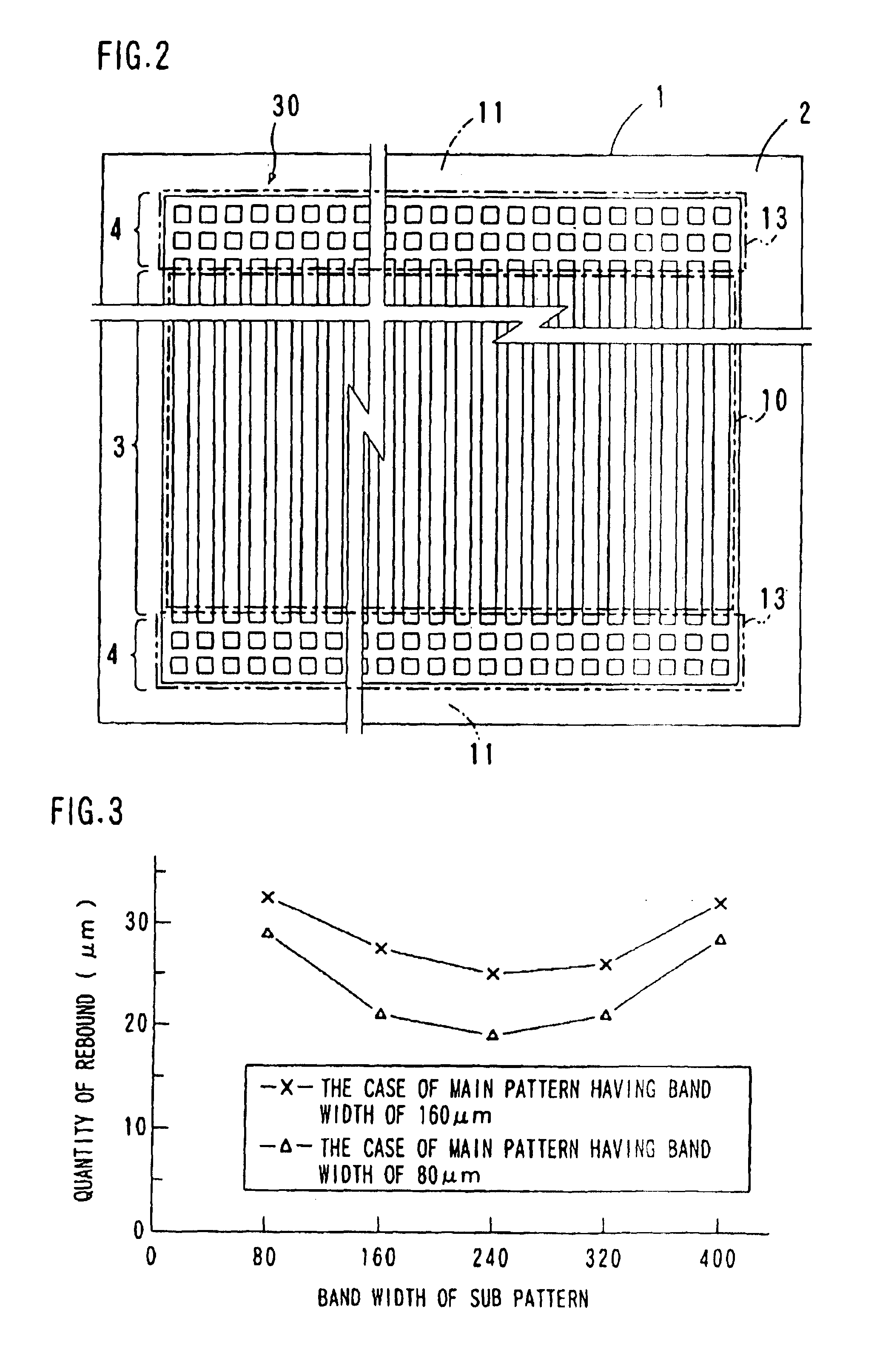
[0031]FIG. 2 is a plan view showing a mask pattern of a first embodiment. A partition pattern of the PDP of the first embodiment is a stripe pattern. The partition is formed basically in the same manner as the conventional process explained with reference to FIG. 12, which includes patterning a sheet-like partition material 2 that covers the entire surface of a glass substrate 1 that is a panel material by using a sandblasting process, and then baking the partition material 2. The difference from the conventional process is that a mask 30 used for patterning extends over a display area 10 and a non-display area 11 at both sides of the display area 10. The display area 10 means an area in which cells are formed on the glass substrate 1, and it corresponds to a display screen of a completed PDP. As to formation of the partition material, 2 there are some methods similarly to the conventional process, i.e., a method of applying low melting point glass paste to the gla...

second embodiment

(Second Embodiment)

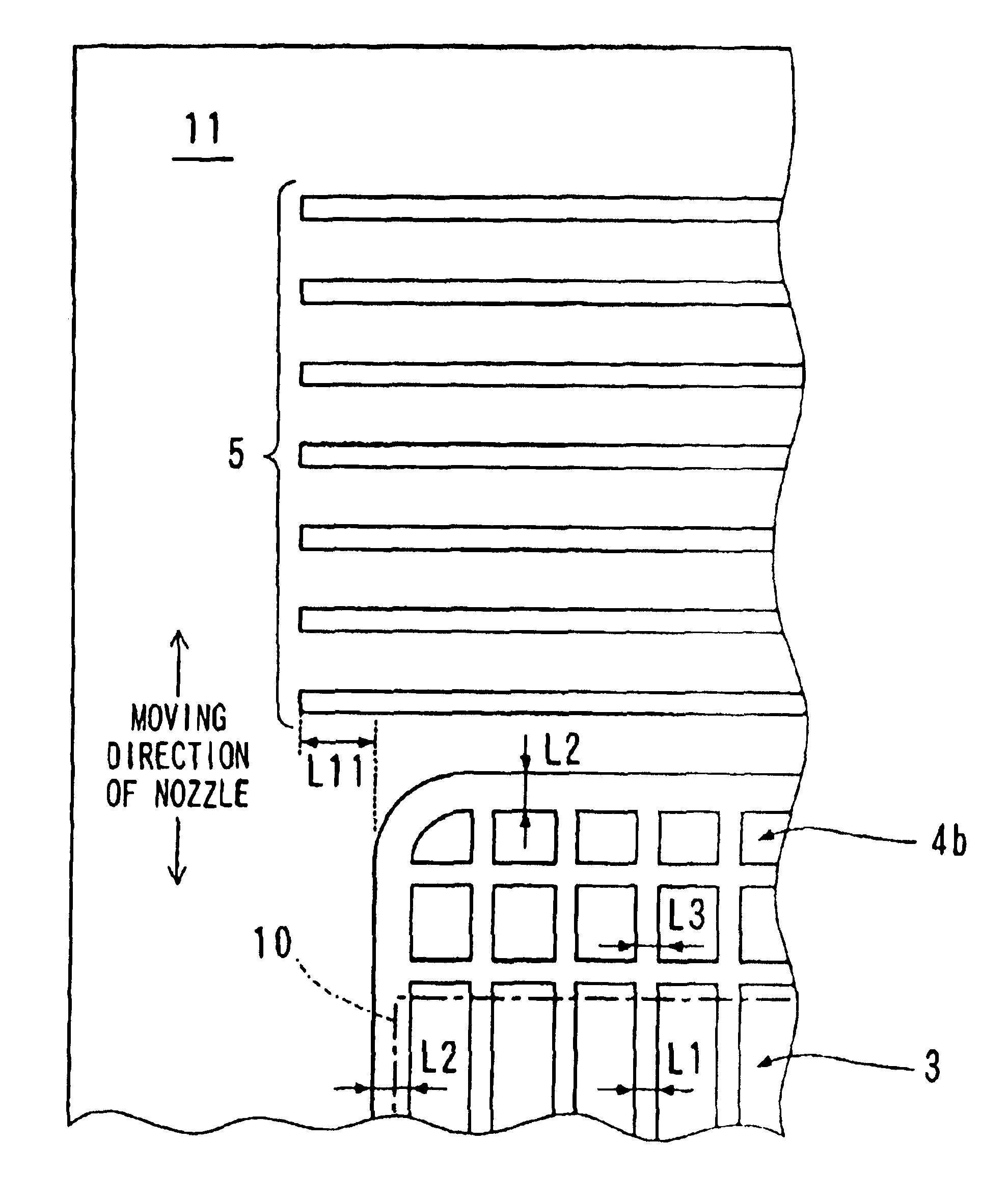
[0036]FIG. 4 is a plan view showing a mask pattern of a second embodiment. FIG. 5 is a diagram showing an enlarged part of the mask pattern of the second embodiment. In the PDP of the second embodiment, the partition pattern is also a stripe pattern. The partition is formed in the same way as the first embodiment, which includes patterning a sheet-like partition material 2b that covers the entire surface of a glass substrate 1b by using a sandblasting process and a mask 30b that is a unit of a main mask 3b and a sub mask 4b, and then baking the partition material 2b. The second embodiment has three characteristics as follows.

[0037](1) At the same time as forming the mask 30b, auxiliary masks 5 are formed at both sides of the mask 30b and separated from the mask 30b.

[0038](2) Among bands that constitute the pattern of the sub mask 4b and are formed in the direction perpendicular to the stripe partition, the most outside band is thicker than bands constituting the p...

third embodiment

(Third Embodiment)

[0050]FIG. 11 is a plan view showing a mask pattern of a third embodiment. The third embodiment is applied to a multiple making process in which partitions for a plurality of PDPs are formed on one substrate simultaneously, and then the substrate is divided. The example shown in FIG. 11 shows an example in which partitions for three PDPs are formed simultaneously, and each of the three display areas 10a, 10b and 10c in FIG. 11 corresponds to a partition portion of one PDP. The partition pattern of the PDP of the third embodiment is also a stripe pattern. The partition is formed by the process in the same way as the first embodiment, which includes patterning a sheet-like partition material 2c that covers the entire surface of a glass substrate 1c by using a sandblasting process and a mask 30b that is a unit of a main mask and a sub mask, and then baking the partition material 2c. The glass substrate 1c has a size of 1460 mm×1050 mm for manufacturing a 32-inch PDP.

[...


PUM


Abstract

A partition is formed by the process including a step for providing a sheet-like partition material that covers a display area and outside thereof on the surface of the substrate, a step for providing a mask for patterning that covers the display area and the outside thereof, so that a pattern of the portion arranged outside of the display area of the mask is a grid-like pattern, a step for patterning the partition material covered partially with the mask by a sandblasting process, and a step for baking the partition material after the patterning.

Description

[0001]Notice: More than one reissue application has been filed for the reissue of patent Ser. No. 10 / 680,136. The reissue applications are Ser. No. 12 / 328,197.[0002]This application is a continuing application, filed under 35 U.S.C. §111(a), of International Application PCT / JP02 / 03362, filed Apr. 2, 2002, it being further noted that foreign priority benefit is based upon Japanese Patent Application 2001-110647, filed Apr. 9, 2001.TECHNICAL FIELD[0003]The present invention is related to a method for forming partitions for manufacturing a plasma display panel (PDP) having partitions in a display area, and the invention can be applied to formation of partition using a sandblasting method.BACKGROUND ART[0004]A surface discharge type PDP that is used for a color display has partitions for preventing discharge interference between neighboring cells. There are two partition arrangement patterns. One is a stripe pattern in which a display area is divided into columns of a matrix display, an...

Claims


Application Information

Patent Timeline
Patent Type & Authority Patents(United States)
IPC IPC(8): H01J9/24H01J11/22H01J11/34H01J11/36
CPCH01J9/242H01J11/12H01J11/36H01J2211/368H01J2211/365H01J9/24
Inventor FUJINAGA, AKIHIROISHIZUKA, KAZUNORIKANAE, TATSUTOSHIIWASAKI, KAZUHIDENANTO, TOSHIYUKIKAWANAMI, YOSHIMISHIBATA, MASAYUKIKUNII, YASUHIKOKOSAKA, TADAYOSHITOYODA, OSAMUSHIRAKAWA, YOSHIMI
Owner MAXELL HLDG LTD
Why Eureka
Try Eureka