
Web member for concrete form walls

a technology of concrete form walls and web members, applied in the field of web members for concrete form walls, to achieve the effects of enhancing strength, reducing material, and strengthening and reinforcing grids

Inactive Publication Date: 2010-12-14
AIRLITE PLASTICS
View PDF34 Cites 10 Cited by
  • Summary
  • Abstract
  • Description
  • Claims
  • Application Information

AI Technical Summary

Benefits of technology

[0017]It has now been discovered that substantial advantages can be obtained where the building component used to build up a concrete form wall comprises bridging members which are engineered to combine an enhanced strengthening and reinforcing grid with a substantial reduction in material. The grid achieves enhanced strength not only from the arrangement of bracing members but also from enlarged openings in the grid allowing improved flow of foam and, subsequently, of concrete.

Problems solved by technology

The components described in that patent include cross members, the ends of which are disadvantageously completely embedded in the foam blocks.

Method used


Image

  • Web member for concrete form walls
  • Web member for concrete form walls
  • Web member for concrete form walls

Examples


Embodiment Construction

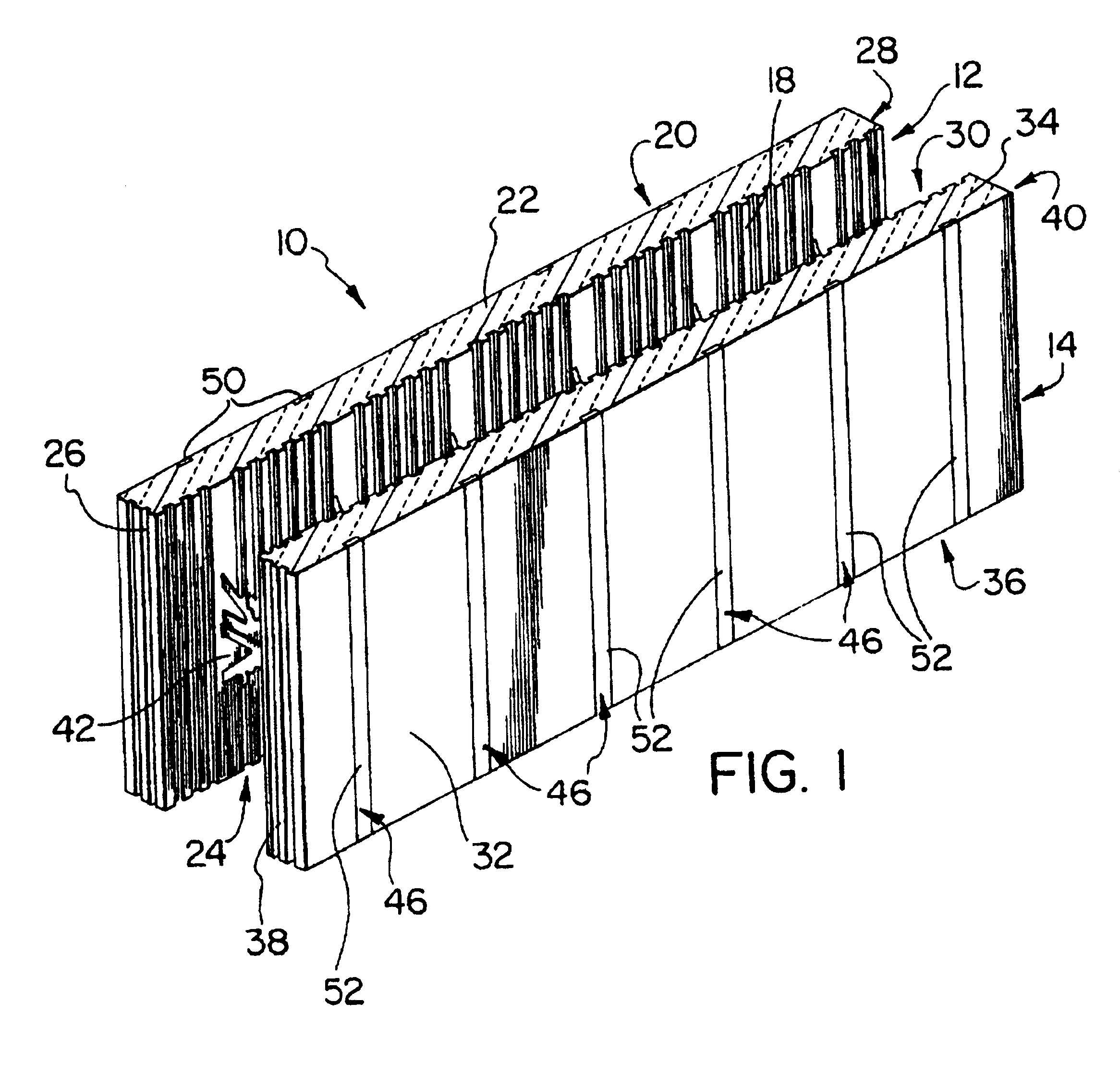
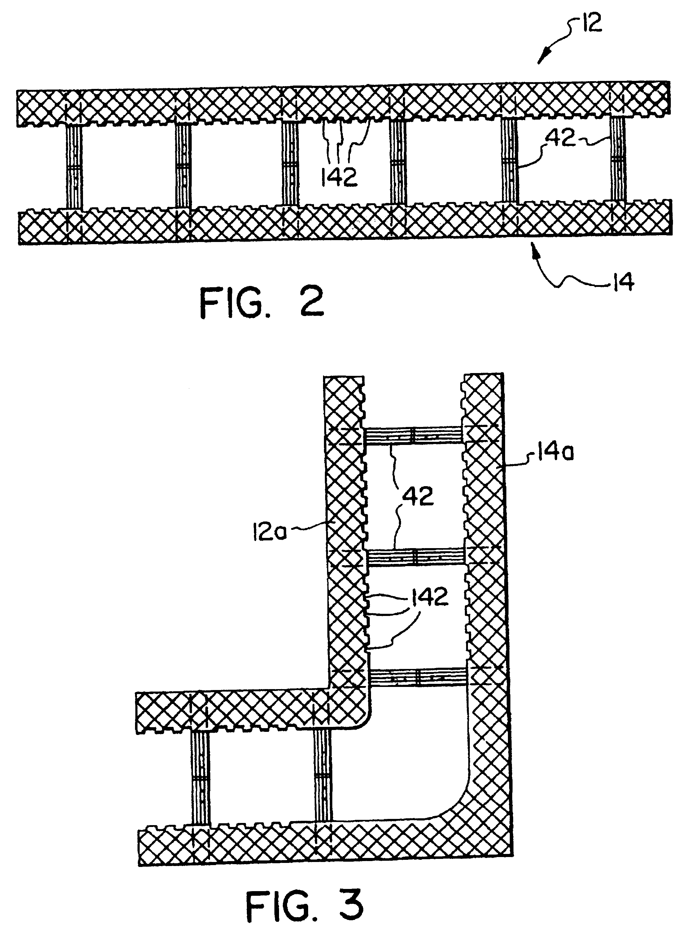
[0042]The building component 10 comprises first and second foam panels 12 and 14 secured together by at least two bridging members 42.

[0043]Panel 12 comprises inner and outer surfaces 18 and 20 respectively, top and bottom 22 and 24 respectively, and first and second ends 26 and 28. Panel 14 comprises inner and outer surfaces 30 and 32, top and bottom 34 and 36, and first and second ends 38 and 40.

[0044]The panels 12 and 14 are preferably fire retardant expanded polystyrene, polyethylene or polypropylene. Subject to indentations and protrusions of minor height to be discussed below, the panels are of uniform rectangular cross-section. In a typical case each panel may be 48 inches long, 16¾ inches high and 2⅝ inches thick.

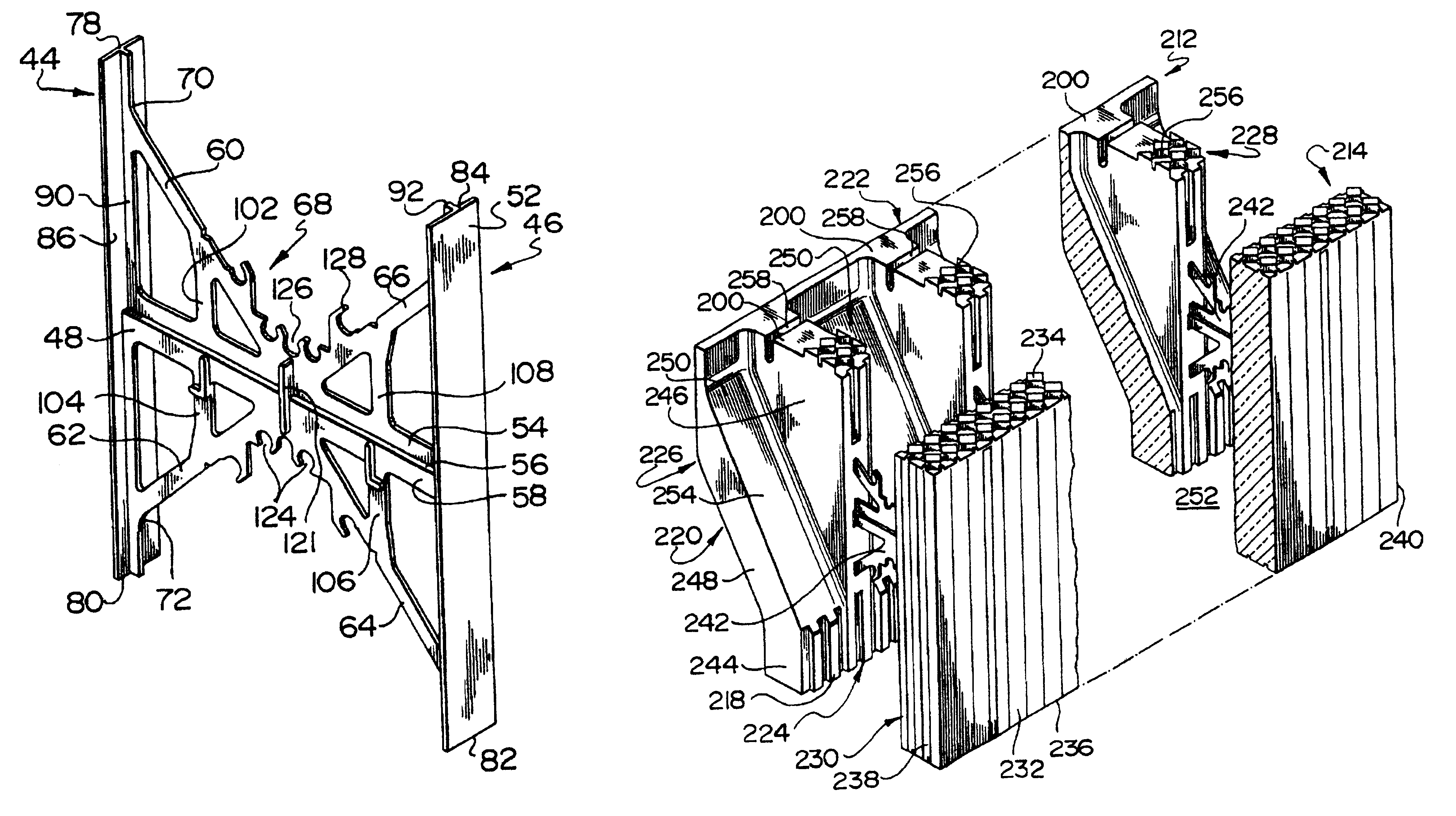
[0045]Bridging members 42 comprise a pair of elongated end plates 44 and 46 joined by narrow strip member 48.

[0046]As illustrated, for example, in FIG. 1, the end plates 44 and 46 have their outer surfaces 50 and 52 respectively substantially flush with the outer su...


PUM


Abstract

The invention provides a building component comprising first and second high density foam panels each having inner and outer surfaces, top and bottom, and first and second ends, the panels arranged in spaced parallel relationship with their inner surfaces facing each other, and at least two bridging members extending between and through and molded into the panel members. Each bridging member comprises a pair of elongated end plates oriented vertically and abutting against the outer surfaces of the panels; a thin narrow strip member joining the mid-areas of the end plates; a series of first narrow bracing members extending from positions adjacent a mid-point of the narrow strip member to positions spaced a short distance from the ends of the end plates; and a series of second narrow bracing members extending from positions on the first bracing members to positions on the strip member intermediate the plates and the mid-point of the strip member.

Description

[0001]This application relates to a building component of the type which is used to build up permanent concrete form walls in building construction.BACKGROUND OF THE INVENTION[0002]In conventional construction in North America concrete walls are normally produced by constructing form walls, pouring concrete into the space between the form walls and, upon the setting of the concrete, removing the form walls. Finishing materials are then added to the concrete walls as required.[0003]Typically in residential construction, concrete basement and other concrete walls will be constructed in the manner discussed above and wood framing will be constructed as required on top of or beside the walls. Insulation will be inserted between the framing members and the wall finished inside and out as desired.[0004]Clearly both parts of this construction are inefficient. It is time-consuming and wasteful of materials to have to remove the form walls after the concrete walls are poured. Furthermore, it...

Claims


Application Information

Patent Timeline
IPC IPC(8): E04B2/00E04B2/02E04B2/86E04C1/40E04G11/06E04G17/06
CPCE04B2/8617E04B2002/0215E04B2002/0263E04B2002/565E04B2002/867E04C1/40
Inventor MENSEN, JAN HENDRIK
Owner AIRLITE PLASTICS
Learn More