
Continuous flow reactor for the synthesis of nanoparticles

a nanoparticle and continuous flow reactor technology, applied in the direction of transportation and packaging, selenium/tellurium compounds with other elements, oxygen/ozone/oxide/hydroxide, etc., can solve the problems of high energy consumption and high cost of deposition system, and the formation of nanoparticles is only done through high energy intensive and expensive deposition system

Active Publication Date: 2021-03-02
SHOEI CHEM IND CO LTD
View PDF26 Cites 0 Cited by
  • Summary
  • Abstract
  • Description
  • Claims
  • Application Information

AI Technical Summary

Benefits of technology

This patent relates to the science and methods needed to create nanoparticles. The invention focuses on developing a system and process for producing nanocrystalline quantum dots that are consistent and repeatable in size and distribution. The technology also includes methods for enhancing the electronic and optical properties of nanocrystalline quantum dots and improving their durability.

Problems solved by technology

An increase in the FWHM means that one of multiple effects could be taking place, such as: large particle size distribution (COV >15%), insufficient degree of crystallinity resulting in trap states that have different energies than a highly crystalline nanoparticle, and inhomogeneity of the material—giving rise to multiple excitations or emissions from the various regions within the nanoparticle or batch of nanoparticles.
Also, nanoparticles may be formed that are not feasible using traditional colloidal nanoparticle synthetic techniques.
Accordingly, the formation of these nanoparticles is only done through high energy intensive and expensive deposition systems such as Atomic Layer Deposition (“ALD”).
Poor coverage by the first shell, or poor lattice matching by the first shell will result in low quantum yields (50%).

Method used


Image

  • Continuous flow reactor for the synthesis of nanoparticles
  • Continuous flow reactor for the synthesis of nanoparticles
  • Continuous flow reactor for the synthesis of nanoparticles

Examples


Embodiment Construction

[0026]Example embodiments will now be described more fully with reference to the accompanying drawings. According to this disclosed embodiment, the process is described in detail for synthesizing nanoparticles such as quantum dots, among others.

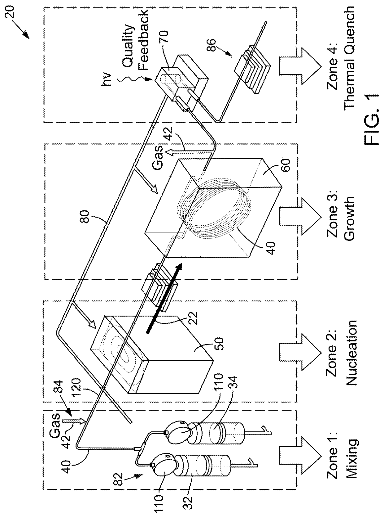
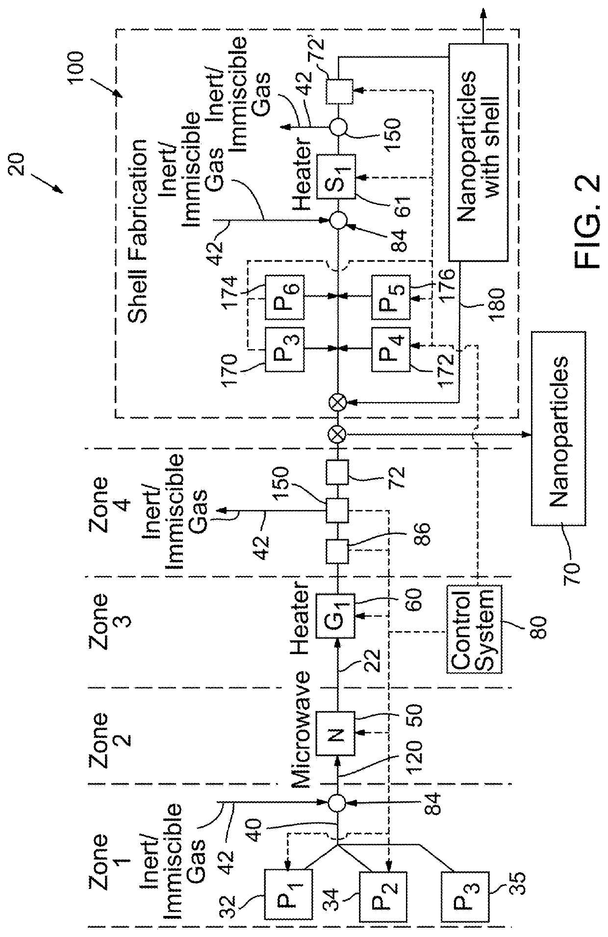
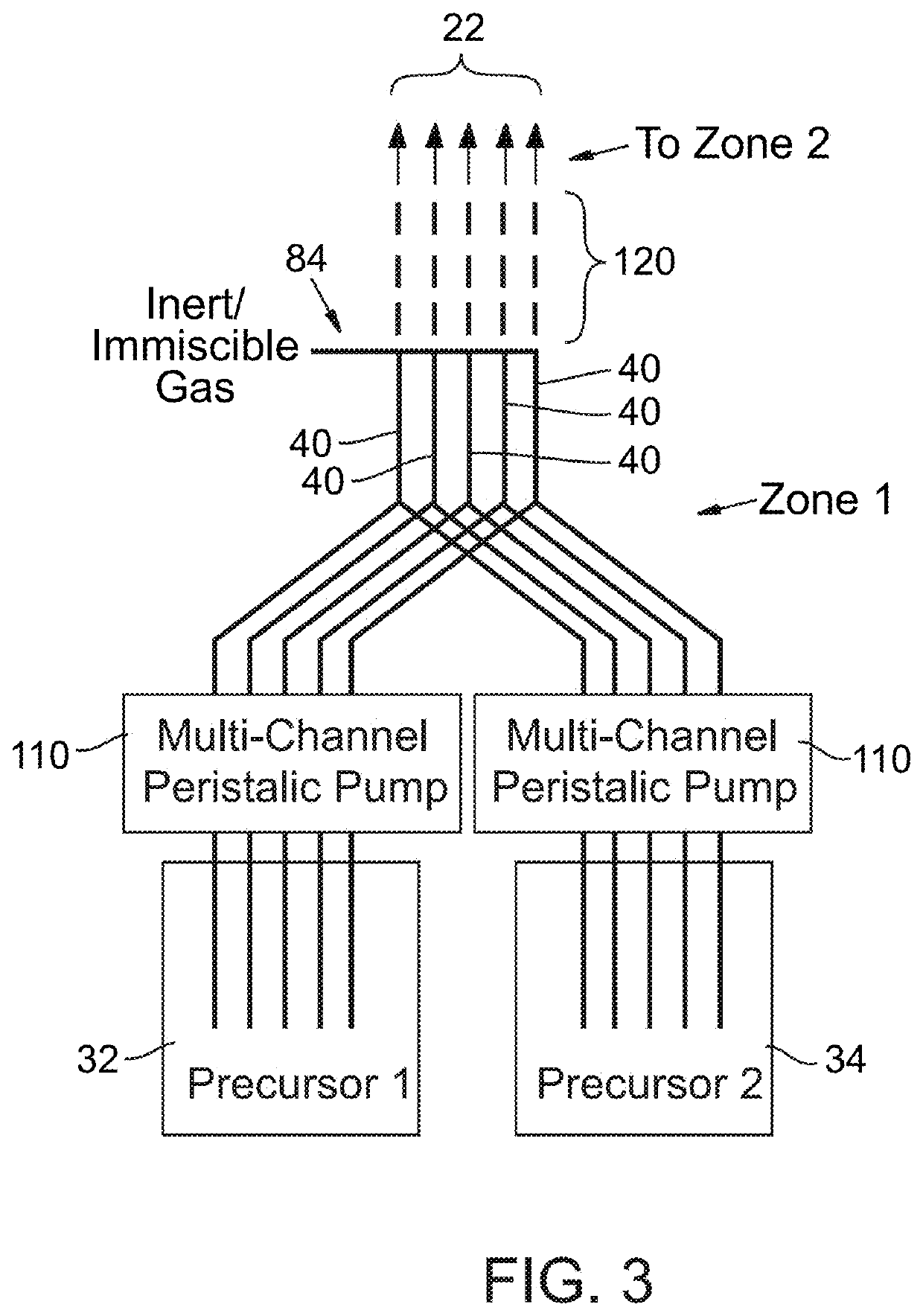
[0027]A continuous flow cell reactor production system for the production of quantum dots and its related components are shown in FIGS. 1-10, 11B and 12B.

[0028]Process Overview

[0029]A conceptual diagram of the nanoparticle production system 20 is shown schematically in FIGS. 1 & 2 and provides a specific example of the system. The system 20 includes a continuous flow path 22 that passes through at least four zones (1-4, respectively). In zone 1, two or more precursors 32, 34 are metered and mixed together and passed through a tube 40 where a reactively inert gas 42 such as nitrogen, argon, and the like may be inserted therein to provide segmented flow of the mixture as it passes to the next zone. For example, in one disclosed embodiment the t...


PUM

PropertyMeasurementUnit
Timeaaaaaaaaaa
Timeaaaaaaaaaa
Timeaaaaaaaaaa

Abstract

A continuous flow reactor for the efficient synthesis of nanoparticles with a high degree of crystallinity, uniform particle size, and homogenous stoichiometry throughout the crystal is described. Disclosed embodiments include a flow reactor with an energy source for rapid nucleation of the procurors followingprecursors to form nucleates followed by a separate heating source for growing the nucleates. Segmented flow may be provided to facilitate mixing and uniform energy absorption of the precursors, and post production quality testing in communication with a control system allow automatic real-time adjustment of the production parameters. The nucleation energy source can be monomodal, multimodal, or multivariable frequency microwave energy and tuned to allow different precursors to nucleate at substantially the same time thereby resulting in a substantially homogenous nanoparticle. A shell application system may also be provided to allow one or more shell layers to be formed onto each nanoparticle.

Description

PRIORITY CLAIM[0001]This applicationMore than one reissue application has been filed for the reissue of U.S. Pat. No. 9,592,555, including the present application and U.S. Reissue application Ser. No. 16 / 159,332, filed Oct. 12, 2018, which is a continuation reissue of U.S. Pat. No. 9,592,555. This application is an application for reissue of U.S. Pat. No. 9,592,555, which claims priority to U.S. provisional patent application Ser. No.Nos. 61 / 783,753; 61 / 783,911; 61 / 784,107; 61 / 784,257; 61 / 784,306; 61 / 784,358; and 61 / 784,183 filed on Mar. 14, 2013, and further this application claims priority to U.S. provisional application Ser. No. 61 / 949,969 filed Mar. 7, 2014; all of the disclosures of which are hereby incorporated by reference.FIELD[0002]The present disclosure relates to a system and method for efficient and continuous production of uniformly-sized nanoparticles which include metal nanoparticles and nanocrystalline quantum dots.BACKGROUND[0003]This section provides background inf...

Claims


Application Information

Patent Timeline
IPC IPC(8): B01J19/12C09K11/56B22F9/16B01J19/00B22F1/00B22F1/02B22F9/24C01B19/00C01G21/21B22F1/054
CPCB22F9/16B01J19/0093B22F1/0018B22F1/0062B22F1/02B22F9/24C01B19/002C01G21/21B01J2219/0086B01J2219/0097B01J2219/00795B01J2219/00869B01J2219/00873B01J2219/00882B01J2219/00889B01J2219/00903B01J2219/00934B01J2219/00941B01J2219/00957B22F2999/00C01P2004/03C01B19/00C09K11/881C01B13/36B01J19/243B01J19/126B01J4/02C01P2004/51B22F1/054B22F2201/11B22F2201/02B22F2202/05B22F2202/11
Inventor SCHUT, DAVID M.NOVET, THOMAS E.WILLIAMS, GEORGE M.
Owner SHOEI CHEM IND CO LTD
Learn More