Connection structure of gas container

A technology of gas container and structure, which is applied in the direction of grounding device, switchgear with metal casing, busbar/line layout, etc., can solve the problems of gas container loss of airtightness, rupture or shrinkage, etc., and achieve the purpose of suppressing thermal deformation and Effects of residual stress, reduction of cracking or shrinkage, reduction of labor and time

Active Publication Date: 2007-10-03
MITSUBISHI ELECTRIC CORP
View PDF5 Cites 0 Cited by
  • Summary
  • Abstract
  • Description
  • Claims
  • Application Information

AI Technical Summary

Problems solved by technology

In addition, if such thermal deformation and residual stress occur in the bushing 53, failures such as cracking and shrinkage (Japanese: ヒケ) will occur, and the gas containers 51 and 52 will lose their airtightness.

Method used


Image

  • Connection structure of gas container
  • Connection structure of gas container
  • Connection structure of gas container

Examples


Embodiment 1

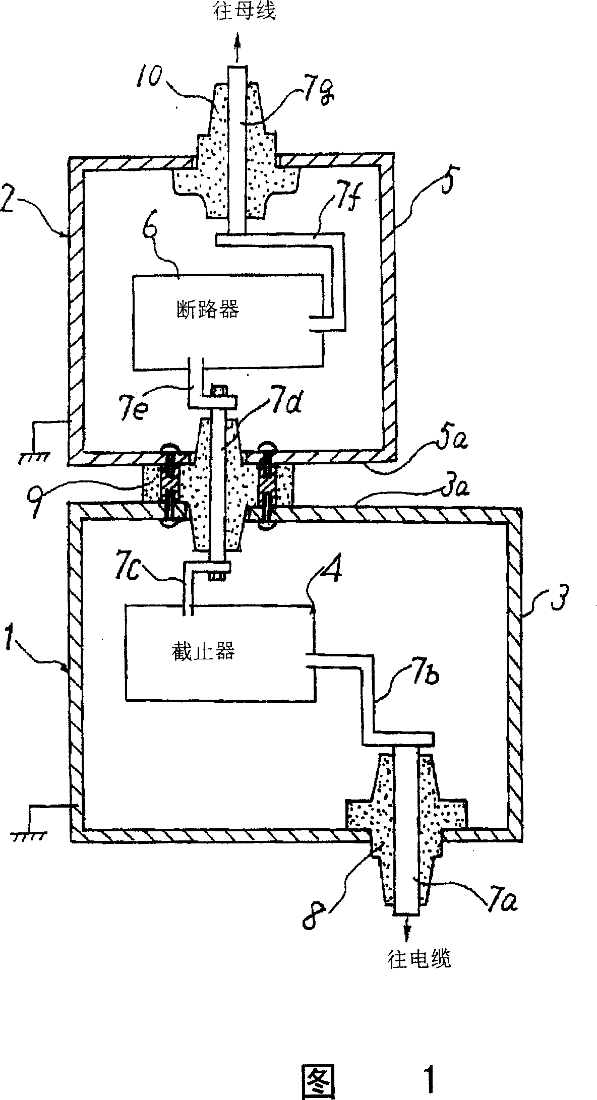
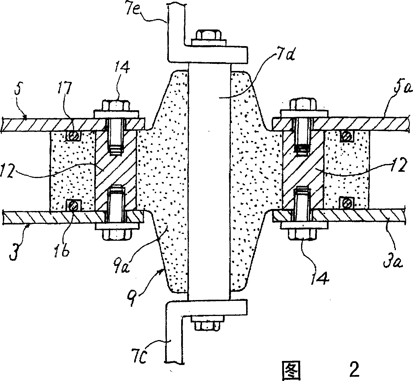
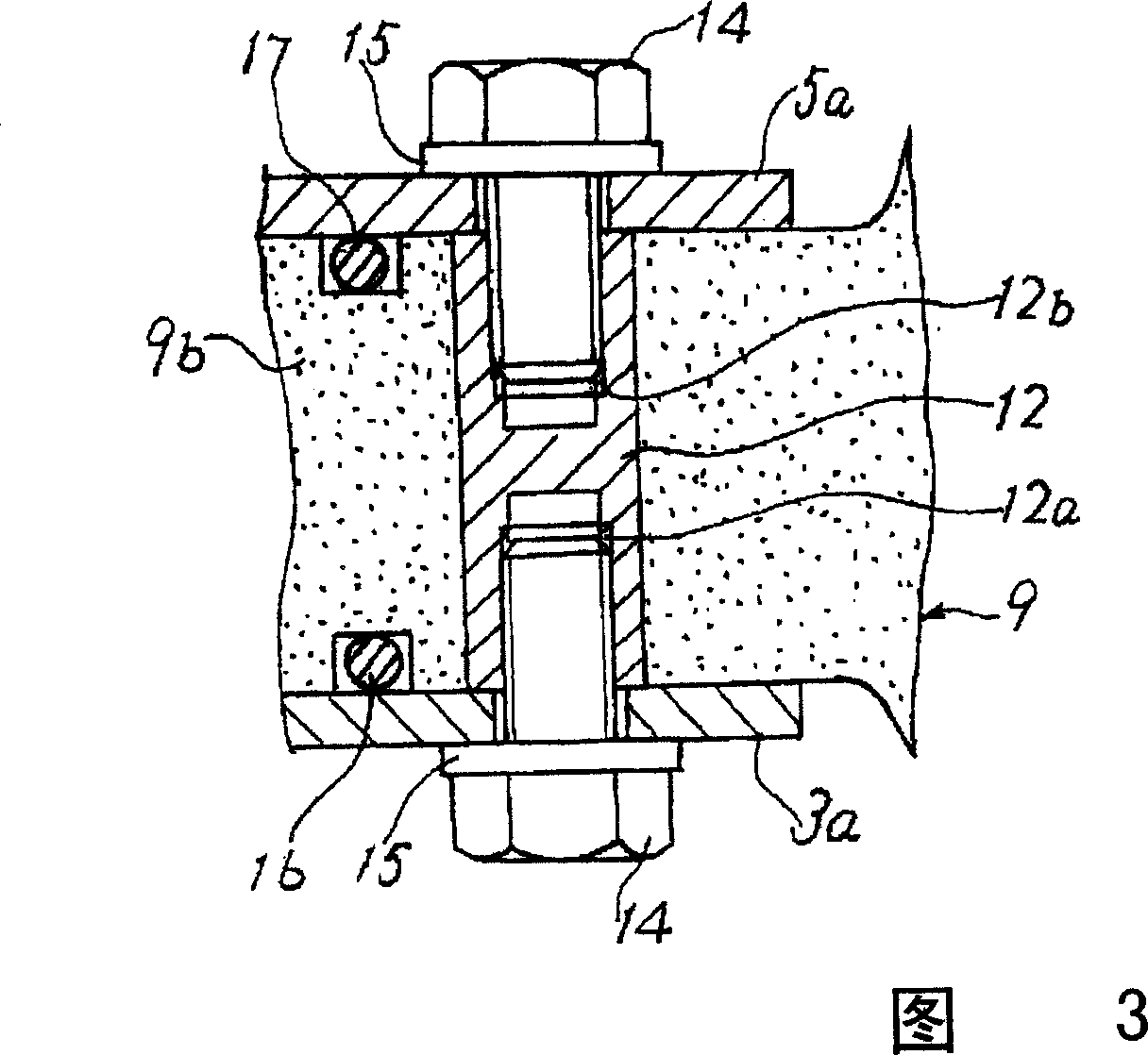
[0020] 1 is a sectional view of a gas insulated switchgear showing a switchgear according to Embodiment 1 of the present invention. FIG. 2 is an enlarged sectional view showing a connection portion of two equipment units constituting the gas insulated switchgear of FIG. 1 , and FIG. 3 It is a cross-sectional view showing only the part where the partition walls of the two gas containers are fixed to the liner in FIG. 2 .

[0021] The gas insulated switchgear of the switchgear according to the first embodiment includes two equipment units 1 and 2 . Furthermore, in one equipment unit 1 , the stopper 4 is accommodated inside the gas container 3 , and in the other equipment unit 2 , the circuit breaker 6 is accommodated inside the gas container 5 . In addition, in each gas container 3, 5, in order to improve the withstand voltage performance of each device 4, 6, for example, an insulating gas such as SF6 gas is sealed.

[0022] In addition, the circuit conductors 7a to 7g are sequ...

Embodiment 2

[0028] Fig. 4 is a cross-sectional view showing only the parts where the partition walls of the two gas containers are fixed to the bushings in Embodiment 2 of the present invention are taken out and shown. For the constituent parts corresponding to Embodiment 1 shown in Figs. 1 to 3, same number.

[0029] The second embodiment is characterized in that the female screw parts 13a, 13b formed from both end surfaces of the embedded metal fitting 13 embedded in the flange part 9b of the bushing 9 and facing inward are not in a state of facing each other, but The positions are shifted from each other in the direction perpendicular to the thickness direction of the embedded metal 13 . The other configurations are the same as those in Embodiment 1, and thus detailed description thereof will be omitted here.

[0030] In the structure of the present embodiment 2, since the thickness of the flange portion 9b of the bushing 9 can be made thinner, in addition to obtaining the functions a...


PUM


Abstract

A connecting structure of the gas vial includes the two vials 3, 5 for containing electric devices 4, 6, a circuit conductor 9 provided through partition walls 3a, 5a adjacent to each other, and an insulating bushing 9 interposed between the circuit conductor 9 and the partition walls 3a, 5a. The inserts 12 are embedded in the bushing 9 in a state that both end faces are exposed to an exterior. Female threaded parts 12a, 12b are formed on the insert 12 from both the end faces toward the inward. The gas vials 3, 5 are coupled integrally to the bushing 9 with bolts 14 engaged with the female threads 12a, 12b. The connecting structure of a gas vial suppresses the occurrence of heat strain or residual stress by reducing the number of inserts which should be embedded in a bushing and which can, moreover, reduces a time and effort and time duration when the inserts are integrally molded in the bushing.

Description

technical field [0001] The present invention relates to a structure for interconnecting a plurality of gas containers accommodating electric devices therein, such as a gas insulated switchgear in which each electric device is housed in a gas container in each circuit unit. Background technique [0002] Conventionally, in switchgear, various electrical equipment such as switches and circuit breakers are housed separately in gas containers, and insulating gas is enclosed in the containers to improve the withstand voltage performance of each electrical equipment. , so as to realize the miniaturization of the whole device. [0003] In such a switchgear, since it is necessary to lead out the electrical connection of the electrical equipment contained in each gas container to the outside of the container, a circuit conductor for connecting the electrical equipment is provided to pass through the inside and outside of the partition wall of each gas container, and, A bushing is pro...

Claims


Application Information

Patent Timeline
Patent Type & Authority Patents(China)
IPC IPC(8): H02B1/16H02B1/20H02B13/02
Inventor 前田多一
Owner MITSUBISHI ELECTRIC CORP
Why Eureka
Try Eureka