Orbital hand tool apparatus for drilling

A technology of manual tools and tools, which is applied in the direction of manufacturing tools, boring/drilling, drilling/drilling equipment, etc., can solve the problems of not providing, cutting tools, bending moments, etc., to reduce the amount of deflection, reduce the The effect of tool length and compact structure

Inactive Publication Date: 2007-10-10
NOVATOR
View PDF7 Cites 0 Cited by
  • Summary
  • Abstract
  • Description
  • Claims
  • Application Information

AI Technical Summary

Problems solved by technology

The idea does not provide a compact and lightweight design
In addition, the various technical solutions shown in the illustrated concept all require a very long tool to be suspended, due to the radial cutting force, which in turn will generate a bending moment on the cutting tool, So this is a serious problem,

Method used


Image

  • Orbital hand tool apparatus for drilling
  • Orbital hand tool apparatus for drilling
  • Orbital hand tool apparatus for drilling

Examples


Embodiment Construction

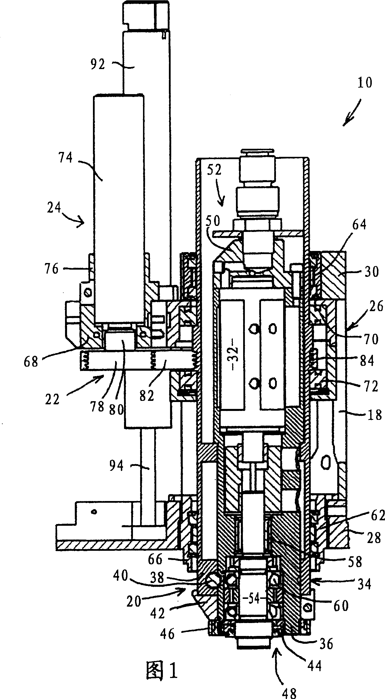
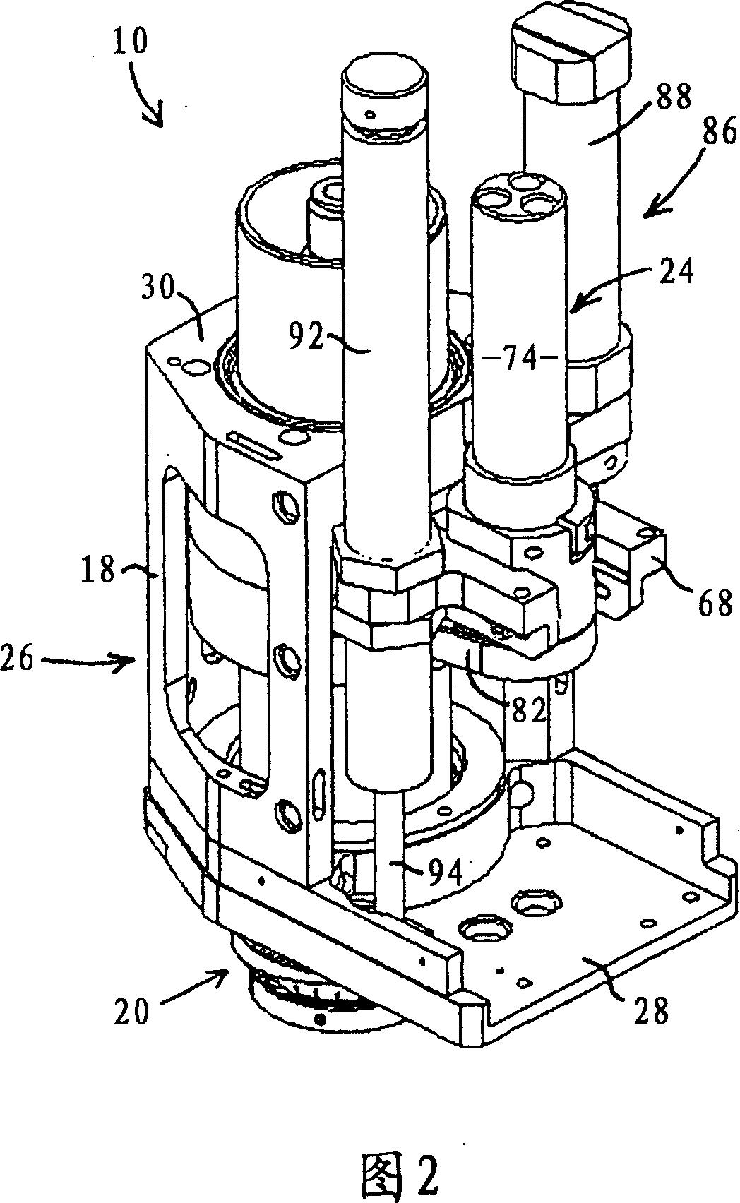
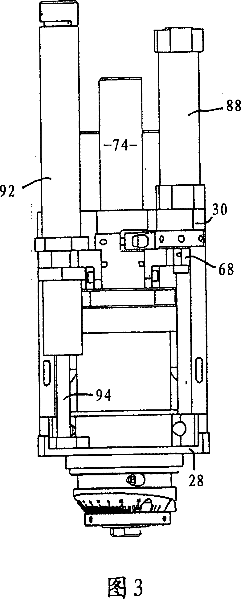
[0025] Referring now to the drawings, a hand tool arrangement in the form of a portable pneumatic orbital drill 10 is shown. The drill 10 includes a shaft member 20 and an eccentric rotation mechanism 22 provided with an orbital drive unit 24 secured to a frame or housing 26 of the drill 10 . The housing 26 includes a bottom panel 28 and a top panel 30 joined together by a wall member 18 . The spindle assembly 20 includes a spindle motor 32 and a radial offset mechanism 34 .

[0026]The radial deflection mechanism 34 generally comprises, in a substantially known manner, an internal bushing 36 in which the shaft part 20 is rotatably mounted. The shaft motor 32 is rotatably supported in an eccentric cylindrical hole provided on an inner sleeve 36 . The eccentric hole has a longitudinal central axis which is parallel to the longitudinal central axis of the sleeve 36 and offset by a certain distance in the radial direction relative to the longitudinal central axis of the sleeve ...


PUM


Abstract

A hand tool apparatus uses a cutting tool with a first width and a tool axis to machine a hole in an object. The hole to be formed has a second width that is larger than the first width of the cutting tool. The apparatus includes a housing (26), a spindle unit (20) in the housing for rotating the cutting tool and an orbital drive (24) for rotating the spindle unit (20). An axial feed mechanism (86) moves the orbital drive (24) and the spindle unit (20) jointly either toward or away from the object being machined.

Description

technical field [0001] The present invention relates to a hand tool for drilling a hole in an object, and more particularly, the invention relates to a hand tool device for cutting a hole with a diameter larger than the diameter of the cutting tool itself. Background technique [0002] US patent 5641252 discloses a method of machining a plurality of holes in a fiber-reinforced synthetic material by using at least one cutting tool, wherein the wear-resistant surface of the cutting tool is positioned eccentrically with respect to a central axis. When the tool is not only rotated around its own axis, but also rotated eccentrically with respect to the central axis, the material is processed both axially and radially by moving the tool in the axial direction. According to a particular feature of the invention, the workpiece is positioned in such a way that the axis of rotation of the tool is substantially perpendicular to the longitudinal direction of the fibers located near the ...

Claims


Application Information

Patent Timeline
Patent Type & Authority Patents(China)
IPC IPC(8): B23B45/00B23C1/20B26F1/16B23B35/00B23B39/00B23B41/00B23B45/14B23B49/02B23C3/34B23Q1/54B23Q1/70B23Q5/04
CPCB23Q1/5468B23C3/02B23B35/00B23B2260/088B23C2220/52B23B49/023B23Q5/046Y10T409/303808Y10T82/125Y10T409/307616Y10T409/304424Y10T408/6757Y10T409/306216Y10T409/307112Y10T82/12Y10T82/122Y10T409/30056Y10T408/172Y10T408/23Y10T408/67Y10T409/304312
Inventor 埃里克·比约克马茨·斯图克斯贝里马库斯·维克隆德
Owner NOVATOR
Why Eureka
Try Eureka