
Wind power generation hydraulic coupling control system and control method thereof

A control system and hydraulic coupling technology, applied in wind turbine control, wind turbine combination, wind power generation, etc., can solve problems such as maintenance difficulties, unstable generator output voltage and frequency, and unfavorable generator grid-connected operation.

Inactive Publication Date: 2007-10-17
LIAONING TECHNICAL UNIVERSITY
View PDF7 Cites 0 Cited by
  • Summary
  • Abstract
  • Description
  • Claims
  • Application Information

AI Technical Summary

Problems solved by technology

[0002] At present, although there are many kinds of wind turbines in the world, they can be divided into horizontal axis wind turbines and vertical axis wind turbines. Their main structures are basically the same, consisting of impellers, gearboxes, generators and towers. The working principle is that the impeller converts wind energy into mechanical energy, and then converts mechanical energy into electrical energy. The main problem of the above two wind power generation systems is that the number of revolutions of the wind turbine changes with the change of wind speed, which leads to the output voltage and frequency of the generator. Instability, which is not conducive to the grid-connected operation of generators; the capacity of a single generator is small; maintenance is difficult, especially when giant or large wind turbines fail, and the maintenance costs are high. Some large wind turbines cannot be put into use because of this; When the wind speed is too low, the system will stop power generation

Method used


Image

  • Wind power generation hydraulic coupling control system and control method thereof

Examples


Embodiment Construction

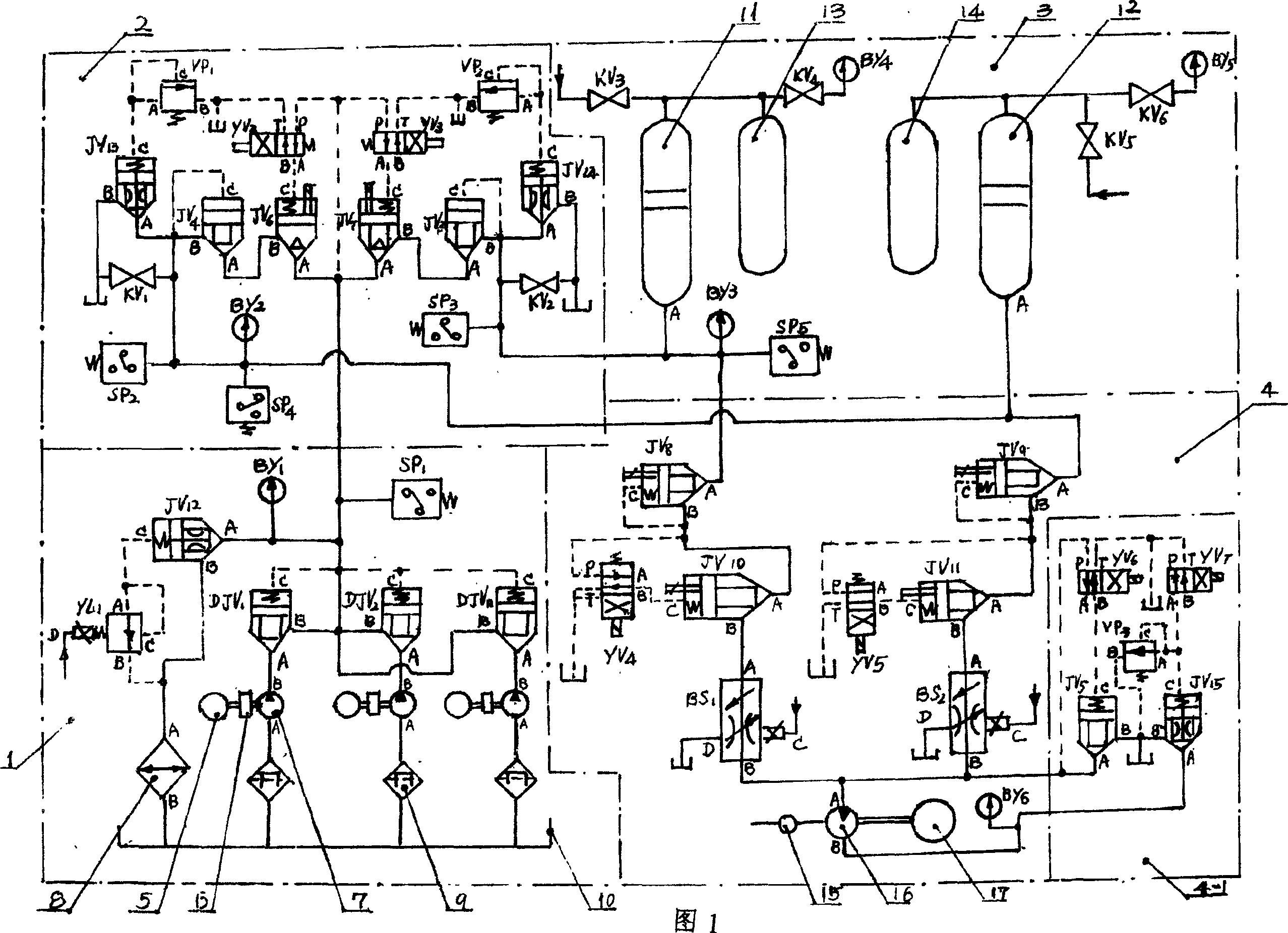
[0009] Referring to the accompanying drawings, a wind power generation hydraulic coupling control system mainly composed of three wind turbines 5, three gearboxes 6, and generator 17 is characterized in that it is between the shaft end of the gearbox 6 and the generator 17. There are hydraulic pump system 1, pressure limiting system 2, pressure compensating and stabilizing system 3, constant current and constant speed system 4 and braking system 4-1. Hydraulic pump system 1, which includes three plunger pumps 7, three filters with magnetic elements 9, three pumps with plug-in one-way poppet valve DJV 1 , DJV 2 , DJV n , Cartridge relief valve JV 12 , pressure switch SP 1 , pressure gauge By 1 , proportional relief valve YL 1 , cooler 8 and oil pool 10; the rotor of the hydraulic plunger pump 7 is fixedly connected to the shaft of the gearbox 6, and a filter 9 with a magnetic filter element is installed between the oil suction inlet of the hydraulic plunger pump 7 and the ...


PUM


Abstract

This invention relates to a wind-generated electricity fluid pressure coupling controlling system, in addition to a controlling method. The controlling system comprises several wind mills (5), gear boxes (6) and generators (17), wherein between the shaft out end of the gear box (6) and the generator (17) it has a hydraulic pump system (1), pressure-limiting system (2), pressure backing-off system (3), constant-current and constant speed system (4) and braking system (4-1); when the rotating number of the wind mill changes with the wind speed, the output voltage and frequency of the generator will be stable, by which the medium-sized wind mill group can constitute large-scale wind-generated electricity system, and its volume can reach to steam generation level; the system end has a pressure compensate system used for ensuring that it has enough torque to output, making the wind mill work long time in its maximum efficiency.

Description

technical field [0001] The invention belongs to a wind power generation control system, in particular to a wind power generation hydraulic coupling control system and a control method. Background technique [0002] At present, although there are many kinds of wind turbines in the world, they can be divided into horizontal axis wind turbines and vertical axis wind turbines. Their main structures are basically the same, consisting of impellers, gearboxes, generators and towers. The working principle is that the impeller converts wind energy into mechanical energy, and then converts mechanical energy into electrical energy. The main problem of the above two wind power generation systems is that the number of revolutions of the wind turbine changes with the change of wind speed, which leads to the output voltage and frequency of the generator. Instability, which is not conducive to the grid-connected operation of generators; the capacity of a single generator is small; maintenan...

Claims


Application Information

Patent Timeline
Patent Type & Authority Patents(China)
IPC IPC(8): F03D7/00F03D9/00F16H61/42F03D9/17F03D9/28F16H61/433
CPCY02E10/725Y02E10/722Y02E10/723Y02E10/72Y02E60/16Y02E70/30Y02P80/10
Inventor 张国军张海华
Owner LIAONING TECHNICAL UNIVERSITY
Learn More