
Fluid coupling

A technology of hydraulic couplings and drive shafts, applied in fluid transmission devices, components with teeth, belts/chains/gears, etc., to achieve the effects of avoiding slip, easy control, and simple structure

Inactive Publication Date: 2007-11-28
EBARA CORP
View PDF2 Cites 0 Cited by
  • Summary
  • Abstract
  • Description
  • Claims
  • Application Information

AI Technical Summary

Problems solved by technology

Therefore, no specific measures have been taken to reduce power loss due to slip

Method used


Image

  • Fluid coupling
  • Fluid coupling
  • Fluid coupling

Examples


Embodiment Construction

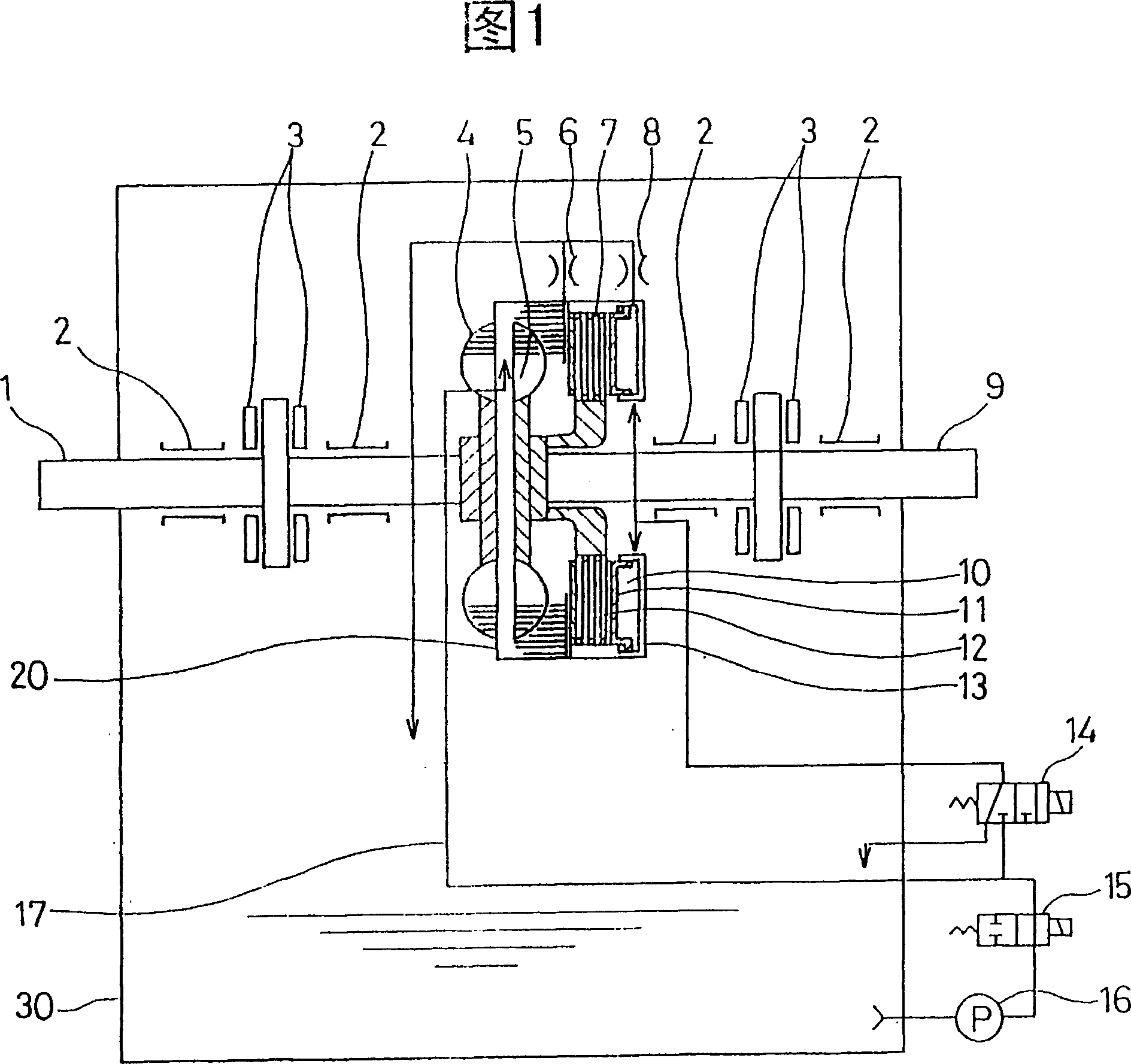
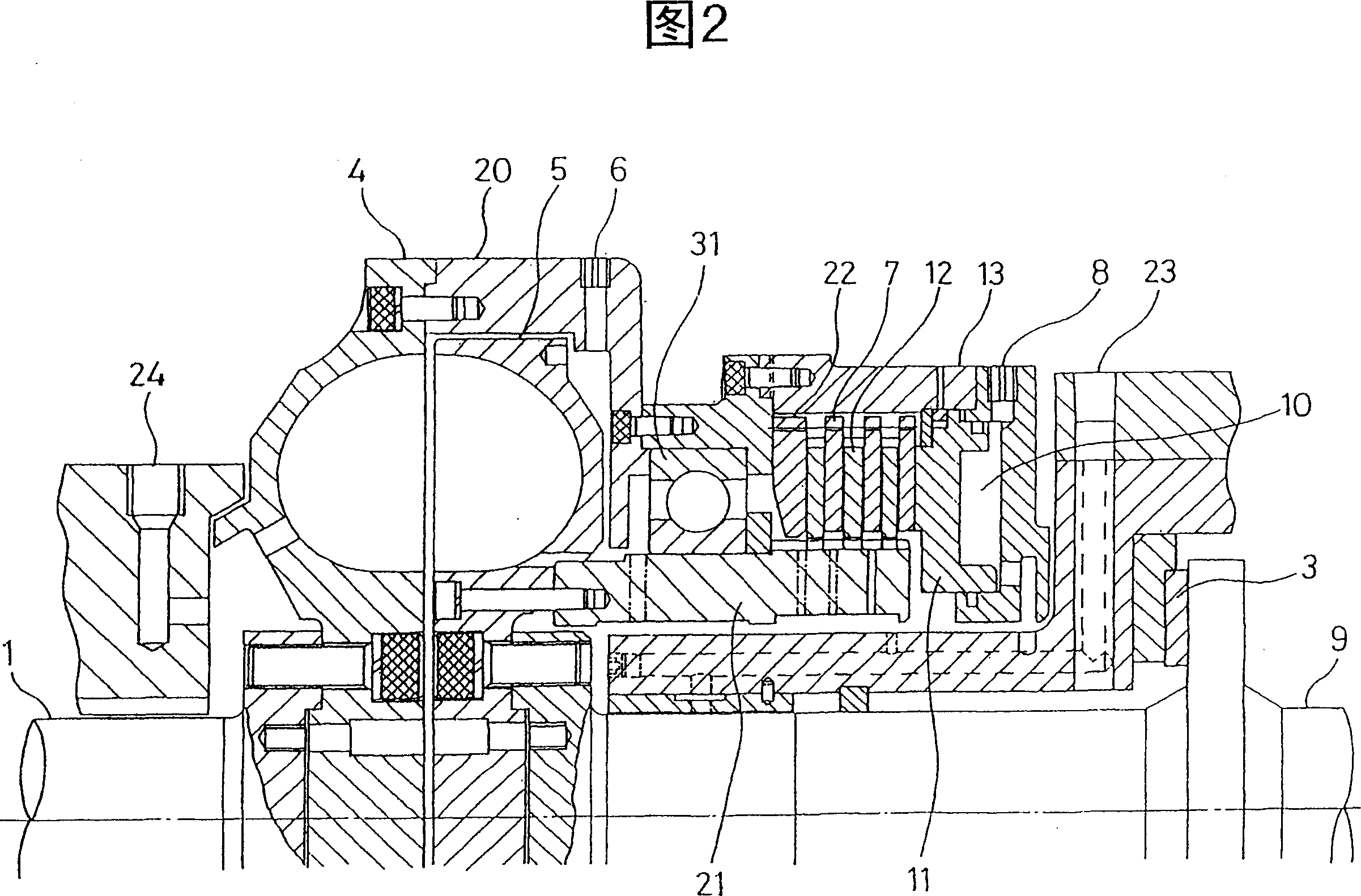
[0022] A fluid coupling according to a first embodiment of the present invention will be described below with reference to FIGS. 1 and 2 .

[0023] The fluid coupling of the present invention has a multi-plate clutch between the drive shaft side and the driven shaft side. When a pressurized fluid such as pressurized oil is supplied to the hydraulic cylinder, the multi-plate clutches are pressed against each other, thereby connecting the clutches. In this case, as a method of generating pressurized fluid, one method is to use the pressure generated by the centrifugal force applied to the oil that rotates with the drive side rotating body, and the other is to use a mechanical connection to the drive shaft Another method is to use the oil pressure generated by a hydraulic pump driven by a motor. The fluid coupling shown in Fig. 1 and Fig. 2 uses the pressure generated by the centrifugal force applied to the oil which rotates together with the driving side rotating body.

[0024...


PUM


Abstract

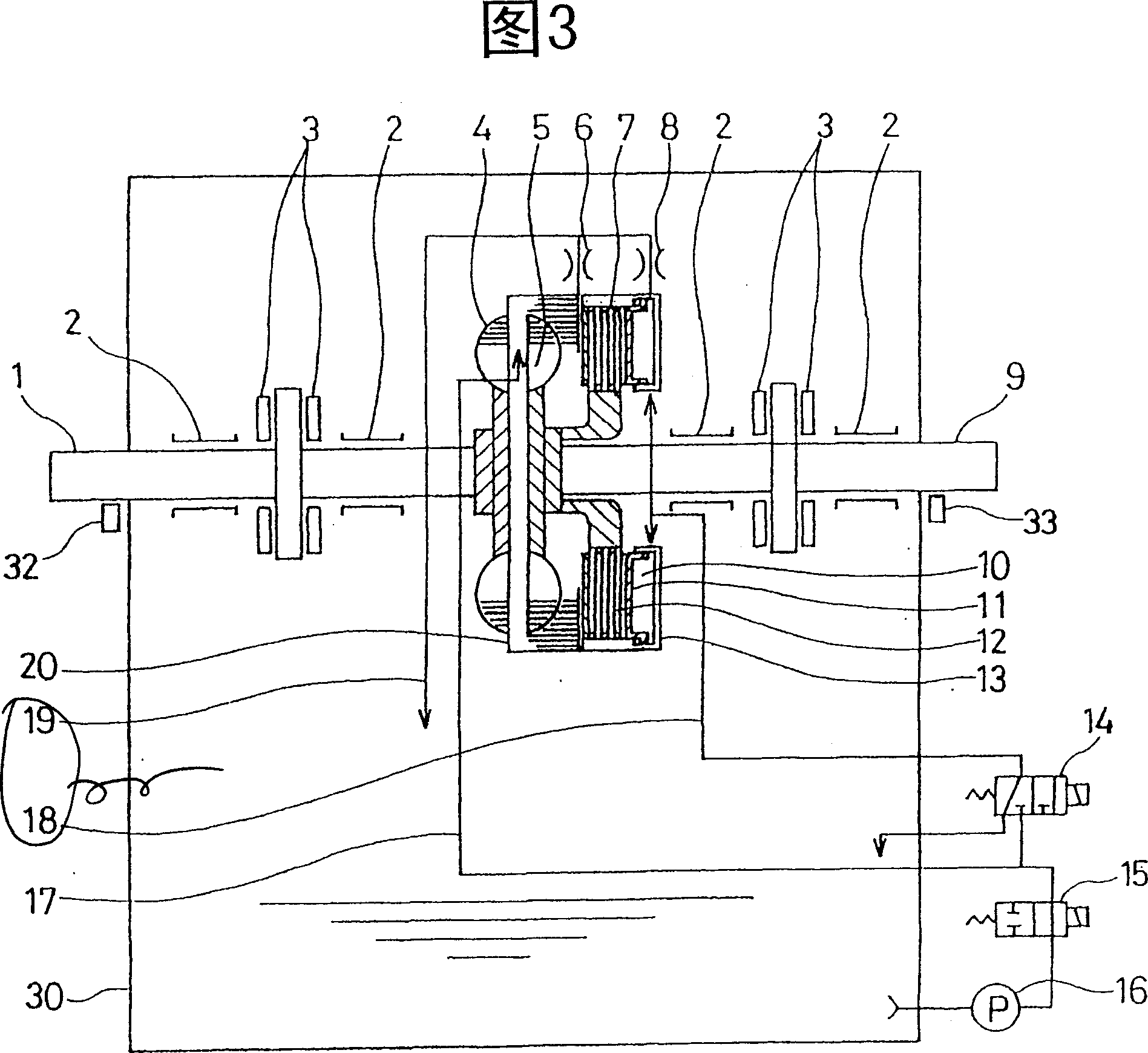
A fluid coupling transmits power from a drive side to a driven side by utilizing kinetic energy of fluid such as oil. The fluid coupling comprises a pump impeller (4) provided on a drive shaft (1), a turbine impeller (5) provided on a driven shaft (9), a housing (20) fixed to the pump impeller (4) and surrounding the turbine impeller (5), and a multiple disc clutch provided between a drive shaft side and a driven shaft side. The multiple disc clutch is operated to couple the drive shaft (1) and the driven shaft (9) mechanically so that the drive shaft and the driven shaft are rotated at the same rotational speed. Thus, the fluid coupling can improve a power transmitting efficiency because of no slip between the rotational speed of the drive shaft and the rotational speed of the driven shaft.

Description

technical field [0001] The present invention relates to a fluid coupling for transmitting power from a driving side to a driven side by utilizing the kinetic energy of a fluid such as oil, and more particularly, the present invention relates to a fluid coupling having a function for coupling with A clutch mechanism in which the driving shaft connected to the prime mover and the driven shaft connected to the driven machine are mechanically connected together, and can improve power transmission by making the speed of the driven shaft equal to the speed of the driving shaft without slip loss efficiency. Background technique [0002] There is known a fluid coupling (fluid coupling) which has a pump pusher connected to a drive shaft and a turbine pusher connected to a driven shaft, and is driven from the drive shaft by fluid filled in a housing The axial driven shaft transmits power. [0003] For example, EP 0 508 528 A1 discloses a fluid coupling with a conventional friction m...

Claims


Application Information

Patent Timeline
Patent Type & Authority Patents(China)
IPC IPC(8): F16H45/02F16H61/14
CPCF16H2045/0284F16H61/14F16H45/02
Inventor 木村克己服部和男绪方大洋形谷吉则杉山和彦
Owner EBARA CORP
Learn More