Overload protecting device and method for speed regulation type magnetic coupling

A magnetic coupler, overload protection technology, applied in emergency protection circuit devices, permanent magnet clutches/brakes, electromechanical devices, etc. and other problems, to achieve the effect of reduced thermal stability, simple design and high practicability

Inactive Publication Date: 2017-05-31
ANHUI UNIV OF SCI & TECH
View PDF6 Cites 4 Cited by
  • Summary
  • Abstract
  • Description
  • Claims
  • Application Information

AI Technical Summary

Problems solved by technology

[0002] In the use of high-power speed-regulating magnetic couplers, when the working machine is stuck or overloaded, the speed difference between the copper rotor and the permanent magnet rotor will increase, which will have a great impact on the working machine, causing the speed-regulating magnetic coupler to fail. The temperature rises, the transmission efficiency decreases, and even affects the service life of the speed-adjustable magnetic coupling
[0003] The invention of patent No. 201510846868 discloses a clutch overload protection device, but it is not suitable for permanent magnet transmissions for automobile gearboxes; the invention of patent No. 200910139671 discloses an overload protection and method, but it is aimed at the internal circuit of the chip system, also not suitable for permanent magnet drives
[0004] The existing overload protection technology has the problem of mismatching with the speed-adjustable magnetic coupler, so it cannot play a good role in overload protection

Method used


Image

  • Overload protecting device and method for speed regulation type magnetic coupling
  • Overload protecting device and method for speed regulation type magnetic coupling
  • Overload protecting device and method for speed regulation type magnetic coupling

Examples


Embodiment Construction

[0032] The present invention will be further described below in conjunction with embodiment and accompanying drawing.

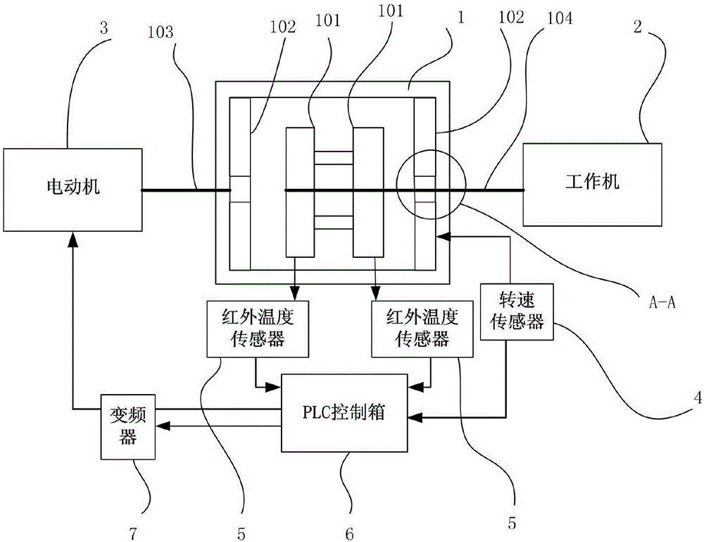
[0033] see now figure 1 , figure 1 It is a schematic diagram of the design of the speed-regulating magnetic coupler protection device of the present invention. As shown in the figure, a speed-regulating magnetic coupler overload protection device includes a speed-regulating magnetic coupler housing 1, a working machine 2, a motor 3, a speed sensor 4, an infrared temperature sensor 5, a PLC control box 6 and a frequency converter 7.

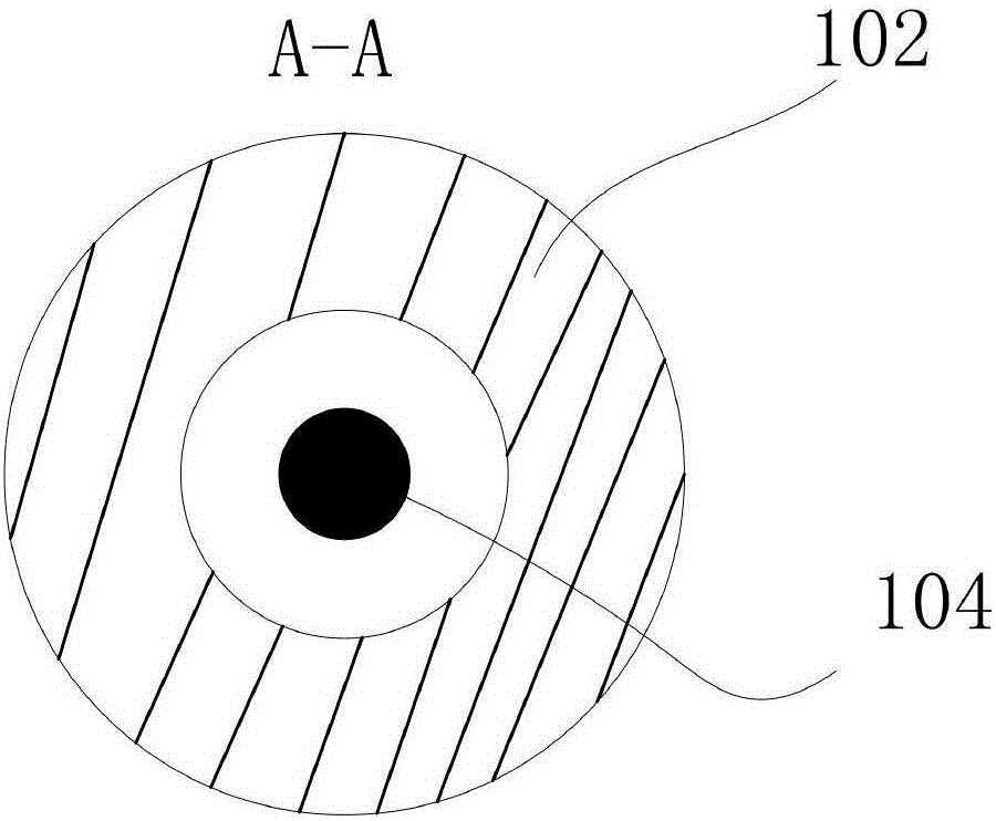
[0034] The speed-regulating magnetic coupling housing 1 includes a permanent magnet rotor 101, a copper rotor 102, an input shaft 103 and an output shaft 104;

[0035] The motor 3 is connected to one end of the input shaft 103;

[0036] The other end of the input shaft 103 is connected to the speed-regulating magnetic coupling housing 1, and the speed-regulating magnetic coupling housing 1 rotates together with the input shaf...


PUM


Abstract

The invention relates to an overload protecting device for a speed regulation type magnetic coupling. The overload protecting device comprises a speed regulation type magnetic coupling, a working machine, an electric motor, a rotation speed sensor, an infrared temperature sensor, a PLC control box and a frequency converter. If the rotation speed of a copper rotor sent by the rotation speed sensor to the PLC control box exceeds a preset protection rotation speed, the PLC control box sends a frequency reducing instruction to the frequency converter, otherwise, the PLC control box sends a frequency invariant instruction; if the temperature of a permanent magnet rotor sent by the temperature sensor to the PLC control box exceeds a preset protection temperature, the PLC control box sends a frequency reducing instruction to the frequency converter, otherwise, the PLC control box sends a frequency invariant instruction; if the electric motor receives a halt instruction, the rotation speed of an input shaft is zero, and then the rotation speed of an output shaft is zero, namely the power is not transferred by the speed regulation type magnetic coupling; otherwise, the electric motor receives a continuous operation instruction, and the speed regulation type magnetic coupling continues to provide powder.

Description

technical field [0001] The invention relates to the field of permanent magnet transmission, in particular to a protection device and method for preventing double-disk magnetic couplings from overloading. Background technique [0002] In the use of high-power speed-regulating magnetic couplers, when the working machine is stuck or overloaded, the speed difference between the copper rotor and the permanent magnet rotor will increase, which will have a great impact on the working machine, causing the speed-regulating magnetic coupler to fail. As the temperature rises, the transmission efficiency decreases, and even affects the service life of the speed-adjustable magnetic coupling. [0003] The invention of patent No. 201510846868 discloses a clutch overload protection device, but it is not suitable for permanent magnet transmissions for automobile gearboxes; the invention of patent No. 200910139671 discloses an overload protection and method, but it is aimed at the internal ci...

Claims


Application Information

Patent Timeline
Patent Type & Authority Applications(China)
IPC IPC(8): H02H7/085H02P27/04H02K49/10
CPCH02H7/0856H02K49/102H02P27/04
Inventor 李德永王爽王鹏彧程刚陈健康方成
Owner ANHUI UNIV OF SCI & TECH
Why Eureka
Try Eureka