
Energy-saving ceramic fire resistant bearing board

A firing plate and refractory technology, applied to lighting and heating equipment, furnace components, furnaces, etc., to achieve the effects of shortening the firing cycle, good strength, and changing the heating state

Inactive Publication Date: 2007-11-28
康健伟
View PDF4 Cites 0 Cited by
  • Summary
  • Abstract
  • Description
  • Claims
  • Application Information

AI Technical Summary

Problems solved by technology

[0003] The technical problem to be solved by the present invention is: increase the heat conduction speed of the setter plate, make the setter products heated evenly, effectively reduce energy consumption and speed up the firing speed, and increase the output; make the products fired in the same kiln have no obvious color difference and small deformation, Thereby improving the product quality; in addition, it is necessary to improve the strength of the setter plate and reduce its breakage rate

Method used

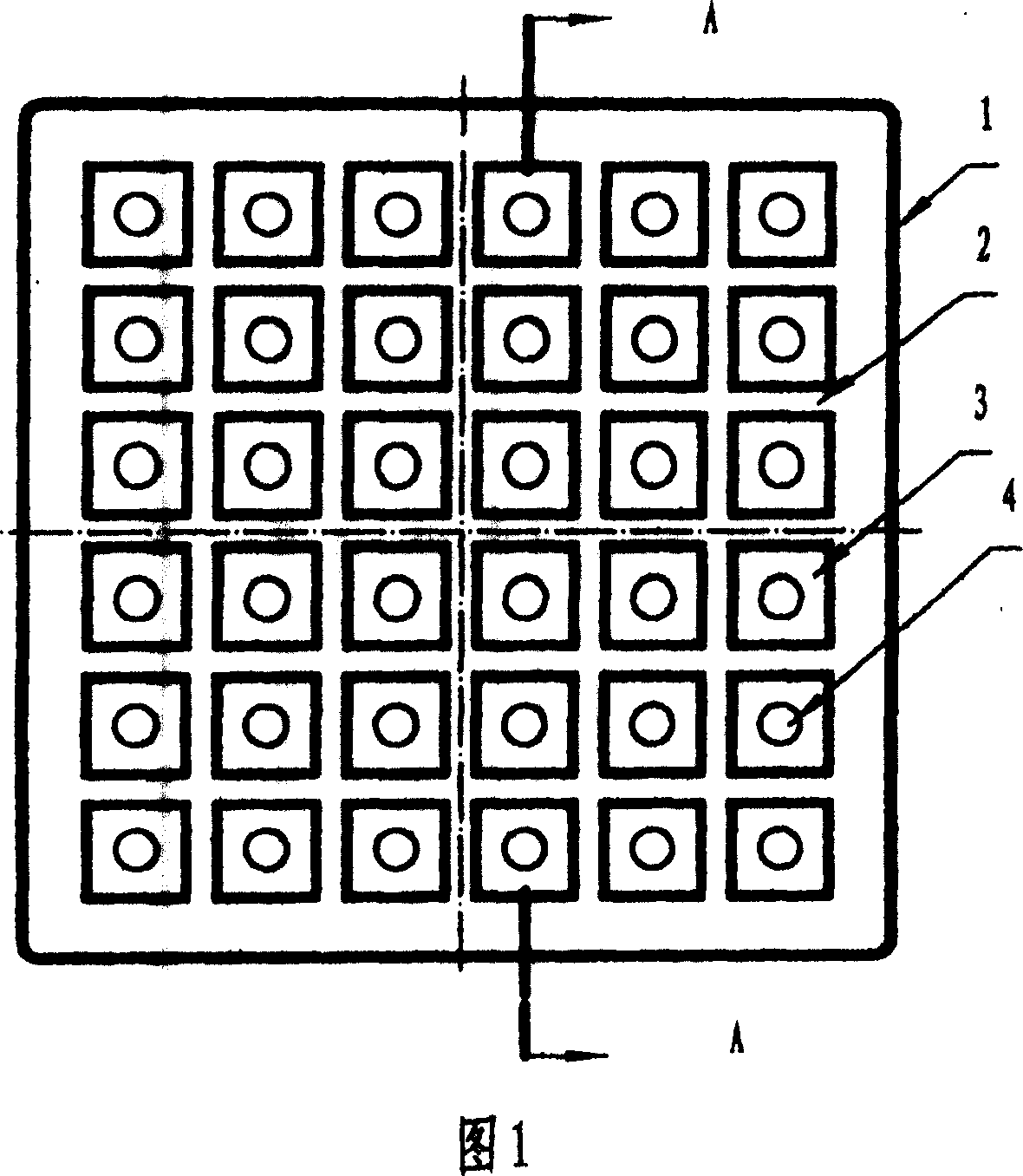
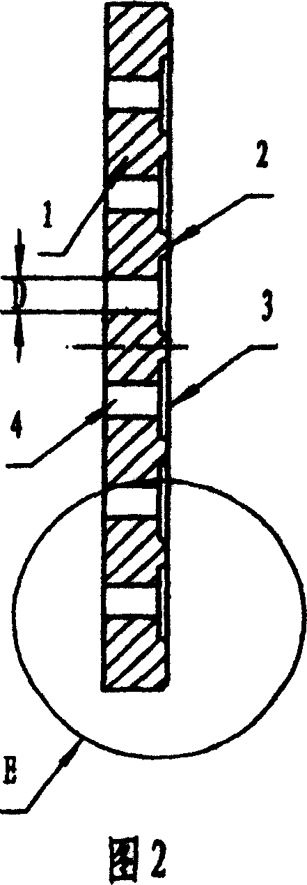
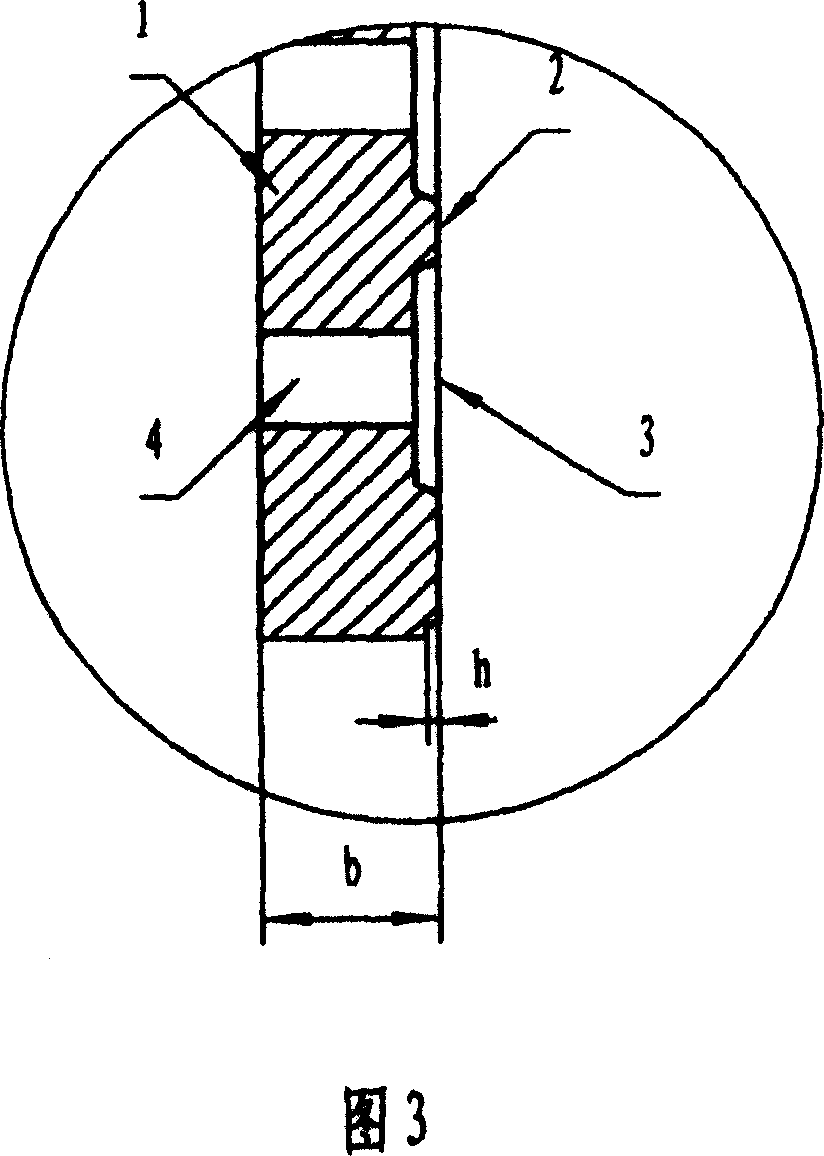

Image

  • Energy-saving ceramic fire resistant bearing board
  • Energy-saving ceramic fire resistant bearing board
  • Energy-saving ceramic fire resistant bearing board

Examples


Embodiment 1

[0020] Referring to Fig. 1, Fig. 2 and Fig. 3, the face of an energy-saving ceramic refractory setter plate 1 is a flat plane, and its bottom plane is covered with ribs 2 vertically and horizontally arranged vertically and horizontally, forming a group of continuous square spaces 3 , a round through hole 4 is arranged in each space 3 . The specification of the setter plate in this example is: 460×460×10mm (length×width×thickness), the specification of each space 3 is 40×40mm, the thickness of the setter plate is b=10mm, and the height of each rib 2 is h=2.5mm , the ratio of rib 2 height h to setter 1 thickness b h b = 2.5 10 = 0.25 . The diameter D of the circular hole 4=10mm.

[0021] The space 3 at the bottom of the ceramic refractory setter plate can be made into regularly arranged squares, rectangles, rhombuses, triangles, polygons, circles, plum blossom...

Embodiment 2

[0023] Referring to Fig. 4, Fig. 5, and Fig. 6, the face of the ceramic refractory setter 5 of the present embodiment is a flat plane, and the bottom plane is covered with ribs 6 arranged vertically, horizontally and obliquely, and each space 7 is provided with A circular through hole 8 is arranged. The specification of the setter plate in this example is: 460×460×13mm (length×width×thickness), the rib 6 height h=2mm, the ratio of the rib 6 height h to the setter plate 5 thickness b h b = 2 13 = 0.15 . The diameter D of the circular through hole 8=12mm.

Embodiment 3

[0025] Referring to Fig. 7, Fig. 8, and Fig. 9, the face of the ceramic refractory setter 9 of the present embodiment is a flat plane, and the bottom plane is stamped with pentagonal spaces 11 arranged regularly, and in each space 11 All are provided with a round through hole 12, and ribs 10 are formed between each space. The specification of the setter plate in this example is: 460×460×8mm (length×width×thickness), the rib 10 height h=4mm, the ratio of the rib 10 height h to the setter plate 9 thickness b h b = 4 8 = 0.5 . The diameter D of the circular through hole 12 is 8 mm.


PUM


Abstract

The invention is an energy-saving ceramic flame-resistant bearing firing plate, for solving the technical problem of making the glazed outside wall bricks fired by the same kiln have no obvious color difference but small deformation, thus improving the quality of finished products, and besides, for strengthening the intensity of bearing firing plate, reducing its breakage rate. For this, the invention fills ribs and blanks at the bottom of the bearing firing plate, where a through hole is equipped within each blank. The blanks and holes can be regularly shaped or irregularly shaped. The invention is mainly used in ceramic kiln to bear and transport the fired ceramic blanks in the course of firing and especially applied to the glazed outside wall blanks.

Description

technical field [0001] The invention relates to the technical field of support components for a combustion chamber of a ceramic kiln, in particular to an energy-saving refractory ceramic setter plate for supporting a ceramic body. Background technique [0002] The firing chamber of the existing ceramic kiln supports the fired ceramic body, such as ceramic exterior wall tiles, mosaic and other glazed brick bodies. These setter plates are all made of refractory materials. Because the bottom and the surface are all flat setters, the heat conduction speed is slow, the heat is uneven, the firing energy consumption is high, the firing time is long, and the output is reduced. Due to uneven heating, the bottom of the glazed brick placed around the setter plate transfers heat quickly, while the bottom of the glazed brick placed in the middle of the setter plate transfers heat slowly, resulting in the overheating of the glazed brick placed around the setter plate. Burning, and the g...

Claims


Application Information

Patent Timeline
Patent Type & Authority Patents(China)
IPC IPC(8): F27D5/00F27D3/12C04B35/48
Inventor 康健伟
Owner 康健伟
Learn More