Supercharge Your Innovation With Domain-Expert AI Agents!

Control system of electric machine for dynamic changing wavecurve of electric machine energized current

A technology of motor control and motor current, applied in control system, AC motor control, single motor speed/torque control, etc., can solve problems such as battery consumption current

Inactive Publication Date: 2008-01-02
WAVECREST LAB LLC
View PDF8 Cites 0 Cited by
  • Summary
  • Abstract
  • Description
  • Claims
  • Application Information

AI Technical Summary

Problems solved by technology

When high torque demand conditions decrease, a return to the high efficiency curve may be delayed until the user recognizes that the high torque curve is no longer required, thus drawing unnecessary current from the battery

Method used


Image

  • Control system of electric machine for dynamic changing wavecurve of electric machine energized current
  • Control system of electric machine for dynamic changing wavecurve of electric machine energized current
  • Control system of electric machine for dynamic changing wavecurve of electric machine energized current

Examples


Embodiment Construction

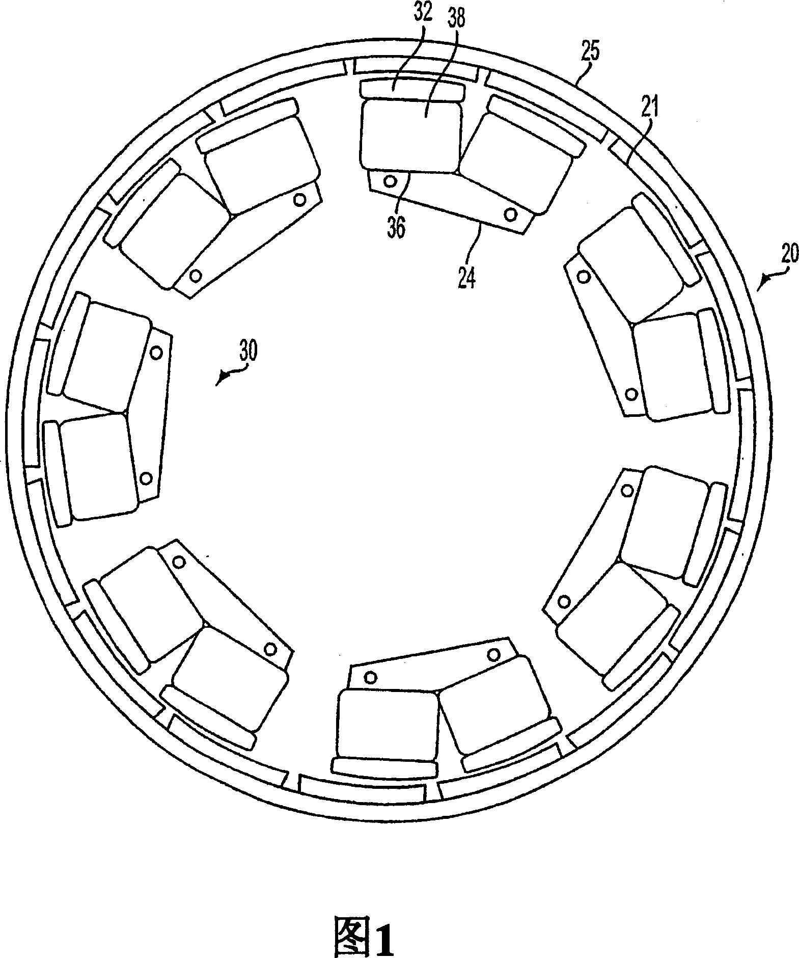
[0024]The present invention is applicable to electric machines such as those disclosed in co-pending application 09 / 826,422, although the present invention may be applied to a variety of other electric machines including permanent magnet machines. Figure 1 is thus an exemplary diagram showing rotor and stator elements as described in this application, the disclosure of which is incorporated herein. The rotor part 20 is an annular ring structure with permanent magnets 21 distributed substantially uniformly along the cylindrical support plate 25 . The permanent magnets are rotor poles that alternate polarity along the inner circumference of the annular ring. The rotor surrounds the stator part 30, the rotor and stator parts being separated by an annular radial air gap. The stator 30 includes a plurality of electromagnet core portions of the same configuration, which are evenly distributed along the air gap. Each core portion includes a generally U-shaped magnet structure 36 fo...


PUM


Abstract

A control system is provided for a multiphase motor having a plurality of stator phase components, each stator phase component comprising a phase winding formed on a core element, and a rotor. A plurality of motor control schemes are stored in memory or calculated dynamically during motor operation. Subject to user or system selection, one of the motor control schemes is selected by a controller for implementation. The controller generates control signals that are applied to energization circuitry for supplying current to the phase windings with a particular current waveform profile in accordance with the selected motor control scheme. The controller has an input terminal for receiving a user initiated torque command signal representing a desired motor torque. Each motor control scheme provides motor driving current that corresponds to torque command signals received at the controller input terminal. In an automatic mode, the controller accesses the appropriate control scheme to meet the torque tracking requirements of the system.

Description

[0001] Related applications [0002] The subject matter contained in this application is related to co-pending US Application No. 09 / 826,423, filed April 5, 2001 by Maslov et al., and co-pending US Application No. 09 / 826,422, US Application No. 09 / 966,102, filed October 1, 2001 by Maslov et al., US Application No. 09 / 993,596, filed November 27, 2001 by Pyntikov et al., 2002 US Application No. 10 / 173,610, filed June 19, and US Application No. 10 / 290,537, Maslov et al., filed November 8, 2002. The disclosures of these applications are incorporated herein by reference. Field of Invention [0003] The present invention relates to the control of electric motors, and more particularly, to the independent implementation of multiple electric motor control schemes for influencing the associated stator current waveforms. Background of the Invention [0004] The co-pending patent application identified above describes the challenges of establishing an efficient motor drive. Electron...

Claims


Application Information

Patent Timeline
Patent Type & Authority Patents(China)
IPC IPC(8): H02P27/00H02P6/08H02P25/02H02P27/06
CPCH02P27/06H02P25/021H02P25/024
Inventor 博里斯·A·马斯洛夫马修·菲姆斯特袁国辉
Owner WAVECREST LAB LLC
Features
  • R&D
  • Intellectual Property
  • Life Sciences
  • Materials
  • Tech Scout
  • Unparalleled Data Quality
  • Higher Quality Content
  • 60% Fewer Hallucinations
Learn More