
Internal combustion type mechanical and electric energy output method and apparatus therefor

A technology of energy output and mechanical energy, applied in the field of internal combustion mechanical and electric dual energy output method and its device, can solve problems such as unreasonable matching, complex system, uncoordinated work, etc.

Inactive Publication Date: 2008-01-23
QINGDAO UNIV +1
View PDF4 Cites 0 Cited by
  • Summary
  • Abstract
  • Description
  • Claims
  • Application Information

AI Technical Summary

Problems solved by technology

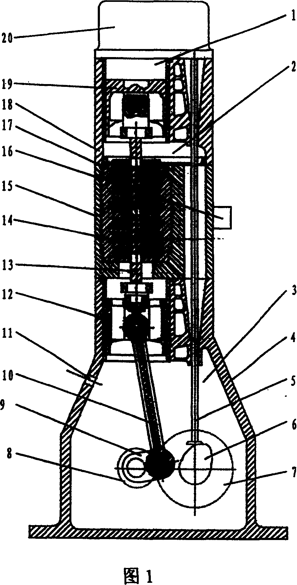
[0004] The purpose of the present invention is to overcome the above-mentioned existing piston type internal combustion generator sets and other energy combined power generation and transmission systems with single function, unreasonable matching, uncoordinated work, low conversion and transmission efficiency, large energy waste, complex system, Bulky, severe wear and tear between parts, high stress strength, large unevenness of system operation and other outstanding shortcomings, seek to design a shunt through the device, directly convert heat energy into mechanical energy and electrical energy, and at the same time can also output mechanical and electrical power separately Dual-element dynamic method and its device

Method used


Image

  • Internal combustion type mechanical and electric energy output method and apparatus therefor
  • Internal combustion type mechanical and electric energy output method and apparatus therefor

Examples


Embodiment 1

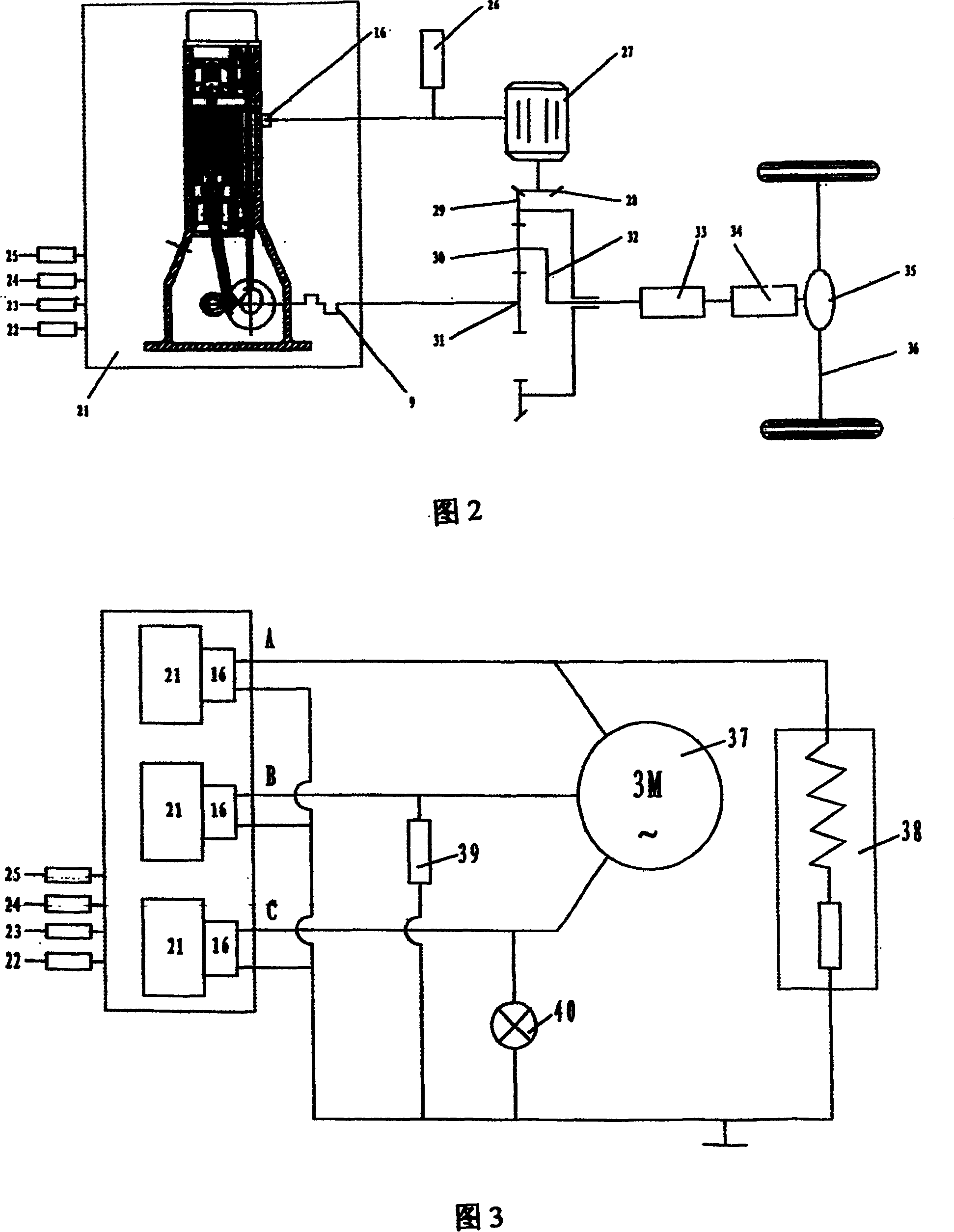
[0026] Example 1: Vehicle Machinery-Electric Hybrid Power Transmission System

[0027] On the energy conversion device 21 involved in the present invention, a fuel supply system 22, a cooling system 23, a lubricating system 24, and an ignition (starting) system 25 are equipped with a conventional technical method, and the power output terminal 16 of the device 21 of the present invention is connected in parallel with a storage battery 26 Constitute the power supply of the generator / motor 27, the mechanical power output end of the generator / motor 27 forms a gear pair through the motor gear 28 and the ring gear 29, and the crankshaft-flywheel assembly 9 is phased with the sun gear 31 of the energy converging device according to the prior art process Connected, the ring gear 29, the sun gear 31, the planetary gear, and the planetary carrier 32 form an energy confluence device, which confluences the mechanical power from the generator / motor 27 and the crankshaft-flywheel assembly 9...

Embodiment 2

[0028] Example 2: Hybrid Power Supply System for Power and Lighting

[0029] On the energy conversion device 21 involved in the present invention, adopt conventional technical method to equip fuel supply system 22, cooling system 23, lubricating system 24, ignition (starting) system 25, control energy conversion device 21 three groups of cylinders involved in the present invention The fuel supply sequence is such that the energy conversion device 21 involved in the present invention forms a three-phase voltage on the power output junction box 16, that is, phase A, phase B, and phase C, which is realized by connecting the three-phase AC voltage according to the wiring requirements of the three-phase asynchronous motor 37 Three-phase power supply; connecting inductive load 38 at junction box 16A to realize single-phase power supply; connecting other resistive loads 39 at junction box 16B to realize single-phase power supply; connecting lighting lamp 40 at junction box 16C to real...


PUM


Abstract

The invention discloses an internal-burning type machine and fluid two-tier power output method and device, which is characterized by the following: the first working chamber finishes the transformation of heat energy into line mechanical energy; the second working chamber finishes the diverting of line mechanical energy and transforms part of line mechanical energy into two paths; one path is transmitted to the third or first working chamber and the other path is transformed into power to output directly according to the electromagnetic induction elementary; the third working chamber finishes the transformation of line mechanical energy into rotary mechanical energy to output through crank-flywheel component; the piston-plunger component in the second working chamber finishes the power diverting function, which anchors the crank-flywheel as well as generates power from the relative movement of rotor component winding coil.

Description

Technical field: [0001] The invention relates to a method and device for converting energy state and realizing dual power output, specifically a method for directly converting thermal energy into mechanical energy and electric energy through internal shunting of the engine, and simultaneously realizing dual output of mechanical and electric power. A power output method and a device thereof for internal combustion type mechanical and electric dual energy output. technical background: [0002] For emergency backup power sources, independent power sources for military and field operations, or mobile power sources for vehicles and ships, piston-type internal combustion generator sets are traditionally used. This device mainly has two energy conversion components and a mechanical parameter conversion connection device. composition. At present, this technical method of converting heat energy to electric energy needs to go through four links. One is to realize the conversion of he...

Claims


Application Information

Patent Timeline
Patent Type & Authority Patents(China)
IPC IPC(8): F02B75/26F02G3/02F01B23/00
Inventor 张铁柱
Owner QINGDAO UNIV
Learn More