Motor dust proof bearing assembly

A dust-proof bearing and motor technology, applied in the direction of bearing components, rigid supports of bearing components, shafts and bearings, etc., can solve the problems of speed reduction, noise reduction, frictional heat generation, reduction of motor service life, and reduction of cycle efficiency, etc. Accurate speed, avoid excessive friction, ensure the effect of service life

Inactive Publication Date: 2008-01-23
SUNONWEALTH ELECTRIC MACHINE IND
View PDF6 Cites 0 Cited by
  • Summary
  • Abstract
  • Description
  • Claims
  • Application Information

AI Technical Summary

Problems solved by technology

However, the combined structure of the upper cover, the positioning ring, the shaft tube and the oil bearing is too complicated, which is not conducive to the assembly work
The most important thing is that the lower edge of the door-shaped upper cover is usually tightly engaged with the cut corner of the top surface of the oil-impregnated bearing, thus blocking the oil re

Method used


Image

  • Motor dust proof bearing assembly
  • Motor dust proof bearing assembly
  • Motor dust proof bearing assembly

Examples


Embodiment Construction

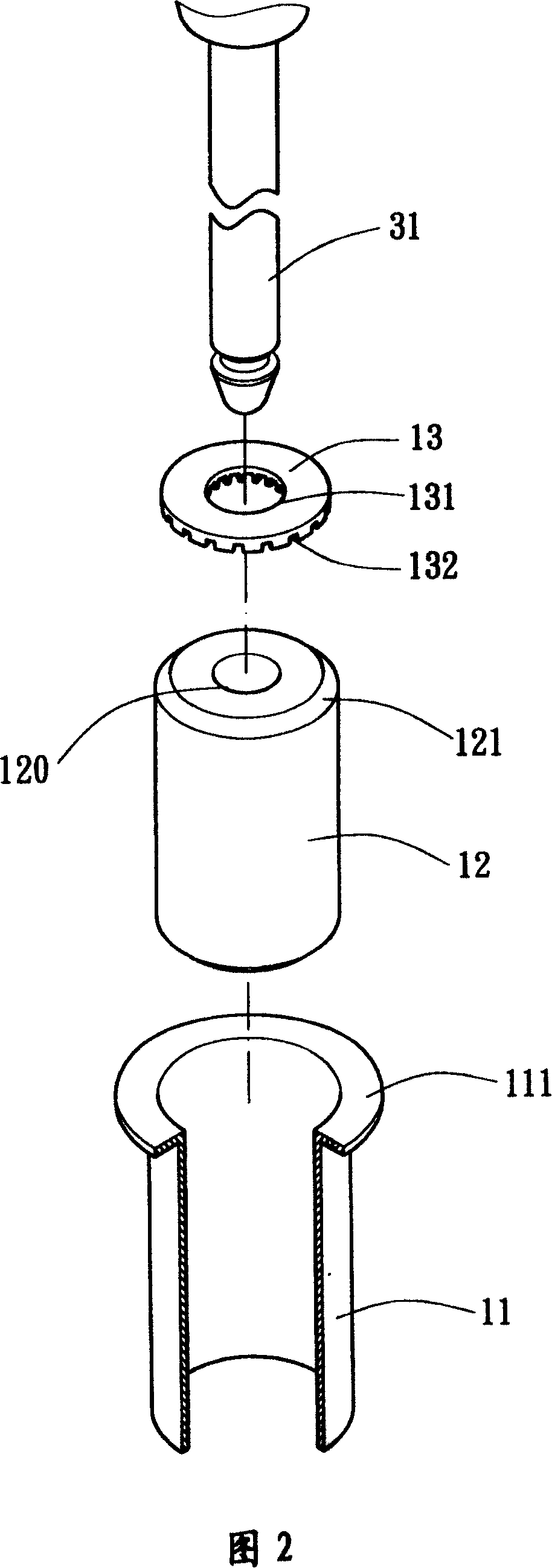
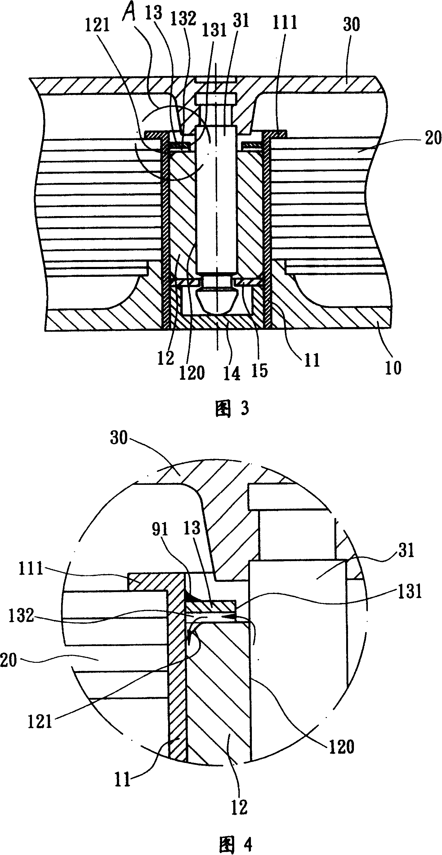
[0022] As shown in FIG. 2 , FIG. 3 , and FIG. 4 , the present invention includes a shaft tube 11 , a sleeve bearing 12 and a dust-proof sheet 13 .

[0023] The shaft tube 11 is a hollow tube with a top flange 111 formed on the top, which can be fixed on the motor base 10 and uses the top flange 111 to lock and position the stator 20 .

[0024] The bearing (sleeve bearing) 12 is selected from various self-lubricating bearings that can store oil, such as copper bearings made by powder metallurgy or ceramic bearings made by sintering. The bearing 12 is provided with a shaft hole 120 through which the shaft rod 31 of the rotor 30 passes, and a chamfer 121 is formed around the top surface of the bearing 12 . The bearing 12 is accommodated in the shaft tube 11 .

[0025] The dustproof sheet 13 can be made of plastic or metal, and has a shaft hole 131 through which the shaft 31 of the rotor 30 can pass and at least one oil return passage 132 . The oil return channel 132 is radially...


PUM


Abstract

This invention relates to a dustproof bearing component for motor. It includes the axis pipe which is in the empty axis pipe. It is in the pipe and locates in the one side of the dust piece. The axle is self-lubricating axle and with hole for rotor axle rod throughing. The dust-proof chip and axle forms a oil back channel.

Description

technical field [0001] The invention belongs to motor components, in particular to a motor dustproof bearing assembly. Background technique [0002] As shown in Fig. 1, a conventional electric motor is composed of a base 10', a stator 20' and a rotor 30'. The base 10' is combined with the shaft tube 11', and at least one bearing (sleeve bearing) 12' is arranged in the shaft tube 11'. Thereby, the shaft 31' of the rotor 30' can pass through the shaft hole 120' of the bearing 12', so that the rotor 30' can be rotatably combined with the base 10'. Usually, the lubricating oil contained in the bearing (sleeve bearing) 12' can follow the rotation of the shaft 31', and sequentially form the inner wall of the shaft hole 120', the top surface of the bearing 12', and the chamfered corner of the top surface of the bearing 12'. 121' flows between the bearing 12' and the shaft tube 11', and then flows back to the inside of the bearing 12'. Therefore, the oil in the bearing 12' can ci...

Claims


Application Information

Patent Timeline
IPC IPC(8): F16C33/82F16C33/78F16C35/06
Inventor 陈文官
Owner SUNONWEALTH ELECTRIC MACHINE IND
Why Eureka
Try Eureka