Blade type optimized designing method of turbine compression fluid machine

A blade profile and optimized design technology, applied to mechanical equipment, components of pumping devices for elastic fluids, liquid fuel engines, etc., can solve complex problems and achieve safe operation and low energy consumption

Inactive Publication Date: 2008-02-20
SHANGHAI JIAO TONG UNIV
View PDF3 Cites 1 Cited by
  • Summary
  • Abstract
  • Description
  • Claims
  • Application Information

AI Technical Summary

Problems solved by technology

In this regard, it can be divided into systems described by ordinary differential equations and systems described by partial differential equations. The latter belongs to the category of optimal control of distributed parameters, which is too complicated to solve practical problems. The former belongs to the optimal control category of concentrated parameters. In the category of optimal control, in general, only numerical solutions can be obtained

Method used


Image

  • Blade type optimized designing method of turbine compression fluid machine
  • Blade type optimized designing method of turbine compression fluid machine

Examples


Embodiment Construction

[0016] The specific embodiment of the present invention will be further described below with the design of a centrifugal fan.

[0017] Fan design air volume: 16Nm 3 / min, inlet temperature: 25°C, inlet pressure: 2.5Kpa(G), outlet pressure: 19.5Kpa(G).

[0018] Follow the steps below to optimize the design:

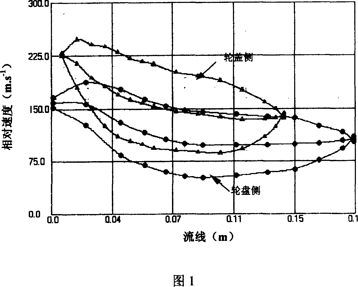
[0019] 1. According to the structural characteristics and design requirements of the centrifugal fan and the aerodynamic parameters of the fan, the flow equation controlled by the N-S equation is simplified: the internal flow of the fan is considered to be relatively constant and non-isentropic, and the effect of local viscous force and the history of viscosity are ignored The influence of accumulation, the influence of the surface of the impeller inside the fan and the growth of the boundary layer of the fan volute, mixing, gap leakage and secondary flow, etc. are all estimated by entropy increase, so that the flow process controlled by the N-S equation is simplified as ...


PUM


Abstract

A method for designing the profile of blade used for turbine-type fluid compressing machinery includes such steps as simplifying the flow procedure controlled by N-S partial differential equation to become the flow procedure controlled by ordinary differential equation, creating state equation, normalizing the equation to become relative optimal control mode, using the installation exit angle of blade as control variable, and iterative calculating to the 3D geometric model of blade and said ordinary differential equation.

Description

technical field [0001] The present invention relates to a blade profile optimization method of a turbocompression fluid machine, in particular to a blade profile design method of a turbocompression fluid machine using the optimal velocity distribution on the surface of the impeller. The impeller designed by the invention can be The compressed fluid machinery has the characteristics of high efficiency, low energy consumption and safe operation. Background technique [0002] Turbine compression fluid machinery (including centrifugal compressors, centrifugal fans, etc.) is the most critical rotating machinery in important industries such as large-scale chemical fertilizers, ethylene, oil refining, coal chemical industry, metallurgical systems, air separation equipment, power generation, and military industry. Performance, reliability and security have always been the focus of attention in the academic and business circles. The high efficiency (including design working conditio...

Claims


Application Information

Patent Timeline
IPC IPC(8): F04D29/30
Inventor 谷传纲杨波王彤毛福芳
Owner SHANGHAI JIAO TONG UNIV
Why Eureka
Try Eureka