Faceplate of liquid crystal display

A liquid crystal display panel, liquid crystal layer technology, applied in static indicators, optics, instruments, etc., can solve the problems of uneven cell gap and high wire height

Inactive Publication Date: 2008-03-05
AU OPTRONICS CORP
View PDF6 Cites 0 Cited by
  • Summary
  • Abstract
  • Description
  • Claims
  • Application Information

AI Technical Summary

Problems solved by technology

[0004] In view of the above-mentioned background, the purpose of the present invention is to provide a liquid crystal panel to solve the problem that the raised structure formed by the overlap of each filter layer and the height of the corresponding wires on the lower substrate are relatively high, resulting in an overall gap between the unit cells. unevenness, and improve the yield and quality of LCD panels

Method used


Image

  • Faceplate of liquid crystal display
  • Faceplate of liquid crystal display
  • Faceplate of liquid crystal display

Examples


Embodiment Construction

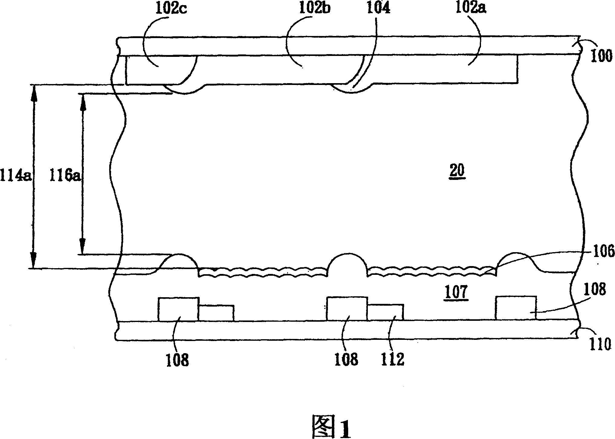
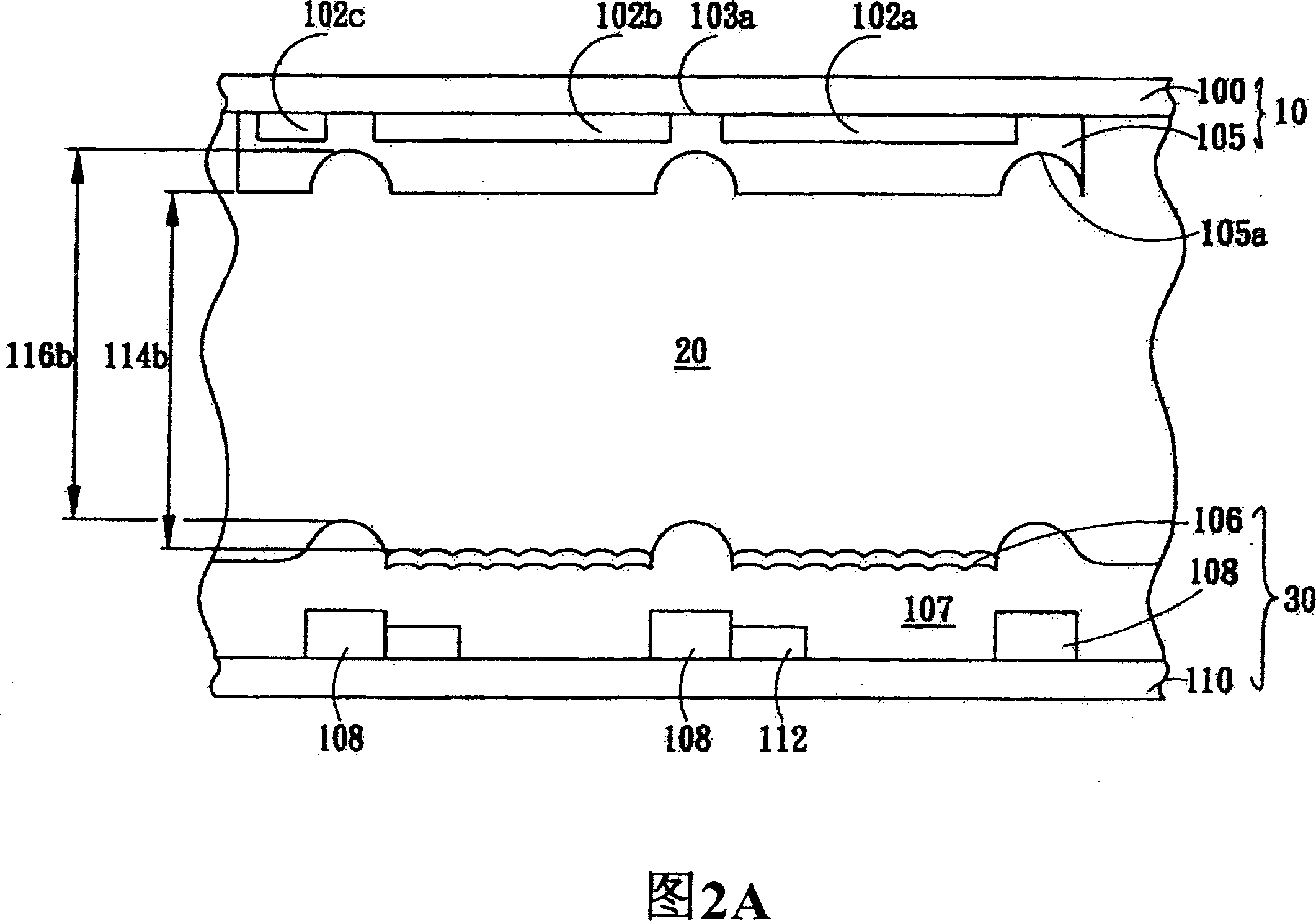
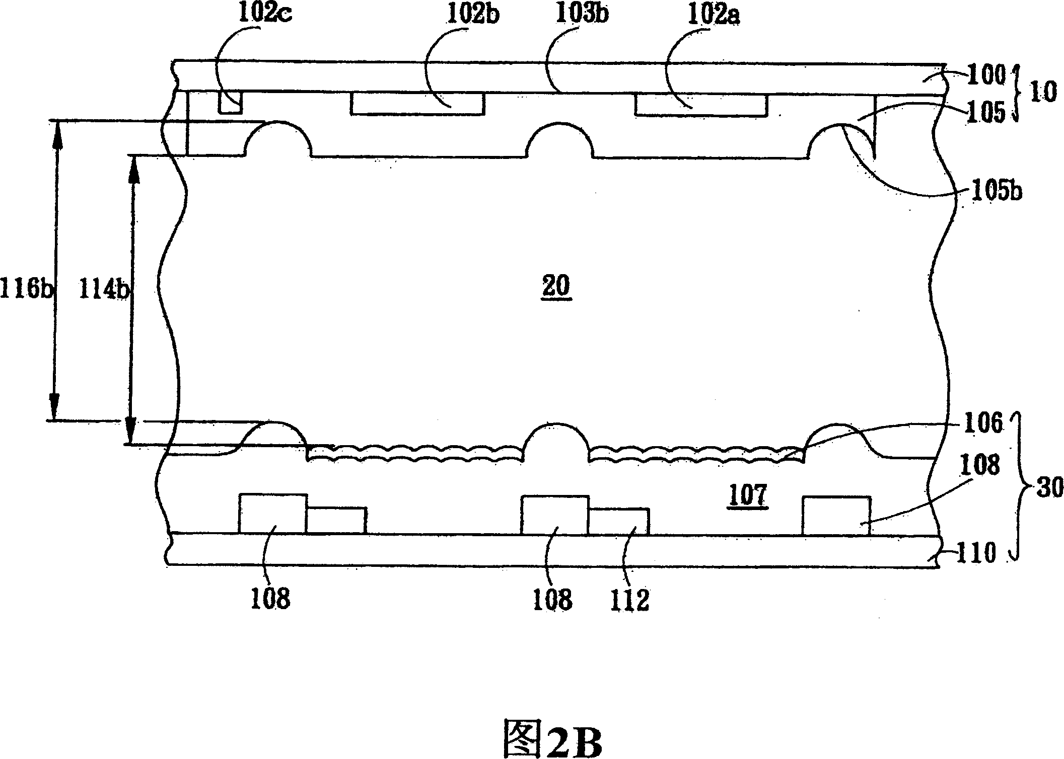
[0033] 2A is a schematic cross-sectional view of an embodiment of the present invention, including a lead substrate 30 with several wires 108, a color filter substrate 10 arranged in parallel above the lead substrate 30, and the color filter substrate 10 has an opening 105a Corresponding to the wire 108 , and a liquid crystal layer 20 fills the gap between the wire substrate 30 and the color filter substrate 10 .

[0034] The lead substrate 30 is composed of a plurality of leads 108 on the lower substrate 110, including data lines and scan lines perpendicular thereto, and a plurality of transistors 112 electrically connected to the data lines and the scan lines. And an insulating layer 107 is formed on the lower substrate 110 to cover the transistor 112 , the wire 108 and the surface of the lower substrate 110 , and the material of the insulating layer 107 can be an organic material. And a reflective layer 106 is formed on the insulating layer 107 in the area defined as the re...


PUM


Abstract

A faceplate of liquid crystal display sets opening on position of wire corresponding to colour filtering substrate to solve problem of convex structure formed by overlap of filtering layers and problem of nonuniformity of gap between liquid crystal particles caused by higher height of wire on bottom substrate corresponding to colour filtering substrate so that the on - specification rate and quality of liquid crystal faceplate can be raised.

Description

technical field [0001] The invention relates to a liquid crystal display panel, in particular to a color filter layer structure in the liquid crystal panel. Background technique [0002] With the increasing demand for liquid crystal displays such as notebook computers (notebooks), monitors and televisions, liquid crystal displays have developed vigorously in recent years, and various liquid crystal displays have been developed according to their light processing modes, such as transmissive liquid crystal displays, Reflective liquid crystal display, transflective liquid crystal display. A liquid crystal display is composed of color filter, glass substrate, polarizer, backlight module, liquid crystal, driving circuit and other components. In the production process of the liquid crystal panel, in order to increase the colors that the liquid crystal panel can display, it is necessary to set various color resistances (or filter layers) on the color filter substrate, such as red ...

Claims


Application Information

Patent Timeline
Patent Type & Authority Patents(China)
IPC IPC(8): G02F1/1335G02F1/133G09F9/00
Inventor 胡至仁
Owner AU OPTRONICS CORP
Why Eureka
Try Eureka