Electrically-controlled variable-focus liquid lens based on electrowetting-on-dielectric

An electronically controlled zoom and fluid lens technology, applied in the lens, optics, instruments, etc., can solve the problems of not having the optical axis self-centering characteristic, the influence of gravity, affecting the position of the optical axis, etc., to achieve low power consumption, low cost, imaging clear effect

Inactive Publication Date: 2008-07-23
TSINGHUA UNIV
View PDF6 Cites 2 Cited by
  • Summary
  • Abstract
  • Description
  • Claims
  • Application Information

AI Technical Summary

Problems solved by technology

However, this structure does not have the self-centering feature of the optical axis, and is seriously affected by gravity. When the device is tilted or shakes, the position of the optical axis will be affected

Method used


Image

  • Electrically-controlled variable-focus liquid lens based on electrowetting-on-dielectric
  • Electrically-controlled variable-focus liquid lens based on electrowetting-on-dielectric
  • Electrically-controlled variable-focus liquid lens based on electrowetting-on-dielectric

Examples


example 1

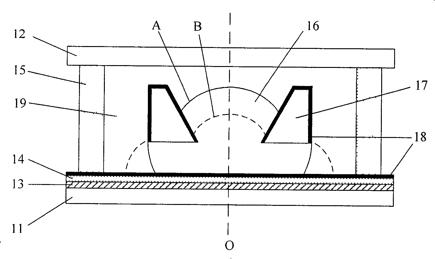
[0041] like figure 1 shown. On a transparent substrate 11, a transparent conductive film 13 and an insulating dielectric film 14 are covered sequentially. Since the selected insulating dielectric film has a certain degree of hydrophilicity, a strong hydrophobic film 18 is also covered thereon. The hollow chamber 15 is filled with an insulating liquid 19 and a conductive or polar liquid 16 . Both liquids are transparent and immiscible, have different indices of refraction and sufficiently similar densities. In order to make the conductive liquid or polarity 16 at the center position, a conductive ring 17 with a through hole is inserted, the bottom surface of the ring 17 is parallel to the substrate 11 and there is a certain gap between them, the conductive or polar liquid 16 is in this gap and in the through hole of circular ring 17. The generatrix of the through hole of the ring 17 can be a straight line with any inclination angle or an arc curve as required. The bottom su...

example 2

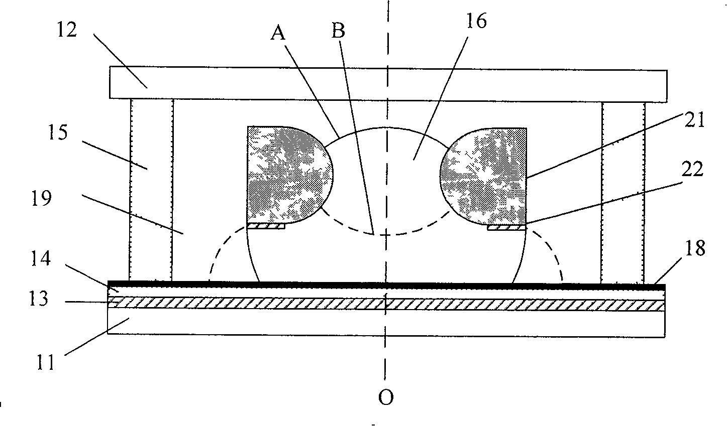
[0045] figure 2 As shown, the transparent substrate 11, the transparent cover plate 12, the transparent conductive film 13, the insulating dielectric film 14, the hydrophobic film 18, the chamber 15, the conductive or polar liquid 16, the insulating liquid 19 and the central axis O etc. figure 1 Same as described in Example 1 shown. The states described by A and B also represent the position of the conductive liquid when no power is applied and a certain voltage is applied, respectively.

[0046] In this example, the insulating ring 21 for stabilizing the conductive or polar liquid 16 also has a through hole with the O axis. Insulation ring 21 can itself have hydrophobicity, also can become hydrophobicity by the method for surface treatment, and its bottom surface is covered with hydrophilic conductive layer 22, to provide an electrical connection with conductivity or polar liquid 16. touch. figure 2 The through-hole generatrix of the circular ring 21 shown is arc-shaped....

example 3

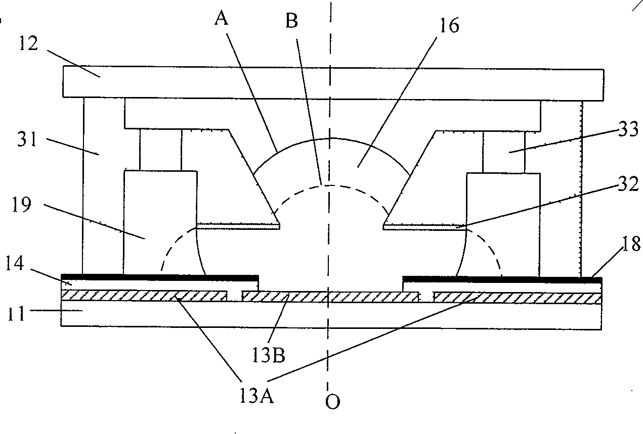
[0048] image 3 As shown, the transparent substrate 11, the transparent cover plate 12, the insulating dielectric film 14, the hydrophobic film 18, the conductive or polar liquid 16, the insulating liquid 19 and the central axis O etc. figure 1 Same as described in Example 1 shown. The states described by A and B also represent the position of the conductive liquid when no power is applied and a certain voltage is applied, respectively.

[0049] In this example, the ring is integrated with the cavity to form a cavity 31 with a central through hole, which simplifies the fixing of the ring. In the chamber 31, several small through holes 33 are distributed around the central through hole, so that the upper and lower parts of the insulating liquid 19 communicate with each other. The bottom surface is given a hydrophilic treatment 32 and the rest is given a hydrophobic treatment. The transparent electrode 13, the insulating dielectric film 14 and the hydrophobic film 18 on the t...


PUM


Abstract

The invention relates to an electric control focal variable fluid lens, based on the medium electric wetting, belonging to the optical focal variable lens. The invention comprises a hollow chamber that containing one conductive or insulated or part insulated ring and two fluids while it is clamped between the transparent basic plate and the transparent cover plate; the transparent basic plate is coated by the conductive film and hydrophobic insulated medium film with special patterns; the bottom of ring has hydrophilous nature, while the top and inner and outer walls have hydrophobic property; the bus of inner wall of ring is a straight line or curve which can be bended in any angle; the ring is parallel with the basic plate and the cover plate with some distance between them. The invention can make conductive or polar fluid in the center by themselves, with simple structure, lower cost, non mechanical movable elements, large focal variable range, high speed, clear image, and lower power consumption. It can be used in photo telephone, endoscope, etc.

Description

technical field [0001] The invention belongs to the field of optical zoom lenses, in particular to an electrically controlled zoom fluid lens based on electrowetting on a medium. Background technique [0002] Camera phones have become one of the most popular consumer electronics products. However, the quality of pictures captured by camera phones is still far from people's expectations. In addition to the low pixels of the CMOS imaging chip used, another major defect of the camera phone is the use of tiny lenses with a fixed focal length, resulting in very poor light collection and resolution capabilities. In order to further improve the imaging quality, in addition to increasing the pixels of the CMOS imaging chip from the current hundreds of thousands to millions, it is an inevitable trend of its development to adopt an optical system with a miniature zoom lens. [0003] Zoom lenses are key components in many optical systems such as cameras, video cameras, microscopes, te...

Claims


Application Information

Patent Timeline
Patent Type & Authority Patents(China)
IPC IPC(8): G02B3/14
Inventor 岳瑞峰康明吴建刚刘理天
Owner TSINGHUA UNIV
Why Eureka
Try Eureka