Self-balanced electronic power transformer

A power electronics and self-balancing technology, applied in the field of power transmission and transformation devices, can solve the problems of affecting the safe and stable operation of the power system, affecting the secondary side power supply, and unfavorable operation of the transformer, so as to improve power quality, flexible transformation, and fast voltage. Effect

Inactive Publication Date: 2008-07-23
HUAZHONG UNIV OF SCI & TECH
View PDF2 Cites 3 Cited by
  • Summary
  • Abstract
  • Description
  • Claims
  • Application Information

AI Technical Summary

Problems solved by technology

These implementations have their own advantages, but there is a common deficiency: when the primary side system is unbalanced, it will be transmitted to the secondary side, affecting the power supply of the secondary side
When the secondary side system is unbalanced, it will also be transmitted to the primary side, affecting the power supply of the primary side
This situation has an impact on the safe and stable operation of the power system, and is also unfavorable to the operation of the transformer itself.

Method used


Image

  • Self-balanced electronic power transformer
  • Self-balanced electronic power transformer
  • Self-balanced electronic power transformer

Examples


example 1

[0026] Example 1: 10kV / 400V three-phase self-balancing power electronic transformer

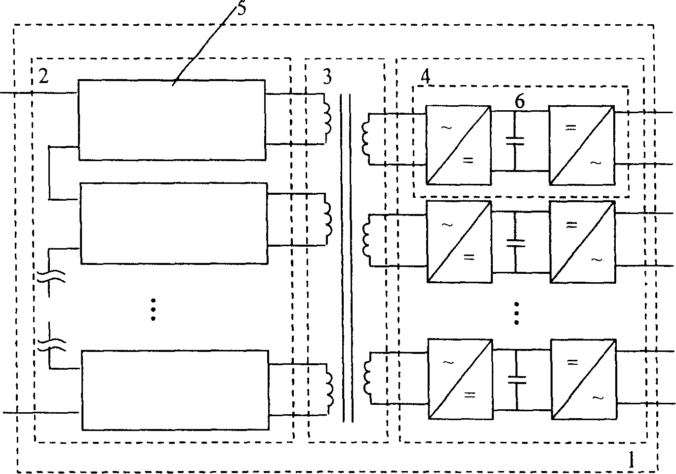
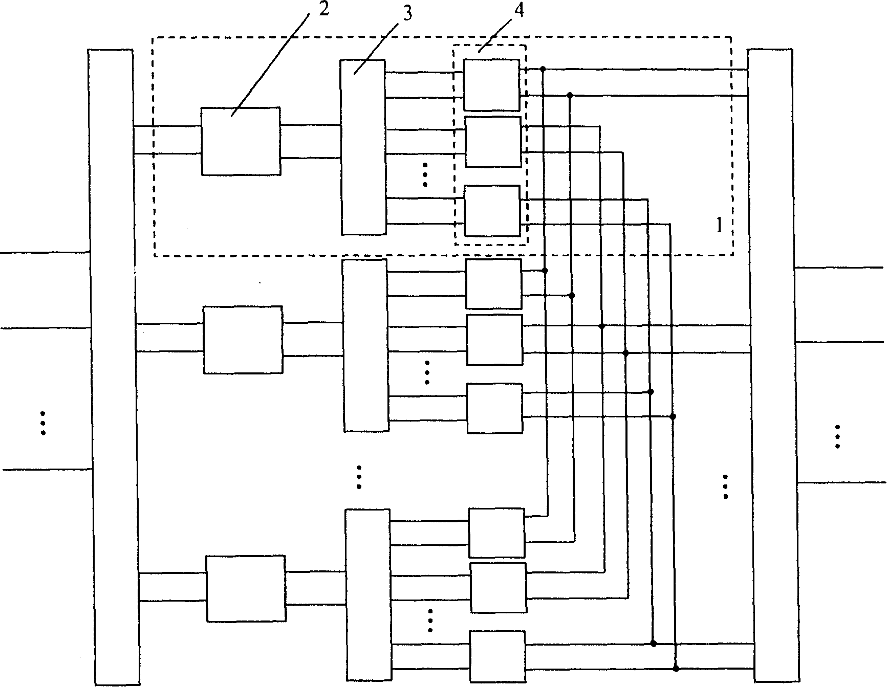
[0027] It consists of three power electronic transformer units that change from one phase to three phases. The high-voltage side adopts star connection, and the low-voltage side adopts star connection with center outlet. The high-voltage stage of each one-phase-change three-phase power electronic transformer unit is 7 AC / DC / AC modules cascaded, the device rated voltage is 3300V, the isolation stage is 7-input 3-output intermediate frequency transformer, and the low-voltage stage is three sets of AC / DC / AC converter, the rated voltage of the device is 1200V. The corresponding low-voltage stages of the three one-phase-change three-phase power electronic transformer units are connected in parallel to form the three-phase output of the self-balancing power electronic transformer.

example 2

[0028] Example 2: 10kV / 220V three-phase to one-phase self-balancing power electronic transformer

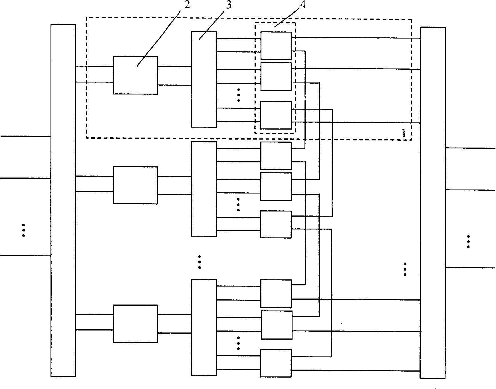
[0029] Consists of three single-phase power electronic transformer units. The high-voltage side adopts star connection, and the high-voltage stage of each single-phase power electronic transformer is cascaded with 7 AC / DC / AC modules, the rated voltage of the device is 3300V, the isolation stage is 7-input 1-output intermediate frequency transformer, and the low-voltage stage is 1 group AC / DC / AC converter, the rated voltage of the device is 1200V. The low-voltage stages of three single-phase power electronic transformers are connected in parallel to form the output of the self-balancing power electronic transformer.


PUM


Abstract

This invention discloses a self-balance electric power transformer, which comprises M one-N phase electric power transformer units formed by star arrangement or polygon; the power transformer is three-level structure of high-voltage level with P converter modules of cascade connection, isolating level of medium frequency or high frequency transformer, and low-voltage level of N independent AC / DC / AC converters. The invention can realize common functions and power dual-direction flow, ensures balance output whatever auxiliary side changes, and quick adjust ability for voltage and current, and has some control ability to current stream.

Description

technical field [0001] The invention relates to a power transmission and transformation device, more specifically to a power transformation device used in a power system. Background technique [0002] Power electronic transformer is a kind of electric energy conversion and transmission equipment that adopts power electronic conversion technology, and it is a new type of power transformer. So far, domestic and foreign researchers have proposed a variety of specific implementation schemes. Such as: Holger Wrede, Volker Staudt, Andreas Steimel. Design of an Electronic Power Transformer. IEEE 2002 28 th Annual Conference of the IECON. Scott D. Sudhoff, Steven F. Glover, Dudley. Galloway. Application of Power Electronics to the Distribution Transformer. Applied Power Electronics Conference and Exposition, 2000. And invention patent ZL 02139030.4. These implementations have their own advantages, but there is a common deficiency: when the primary side system is unbalanced, it ...

Claims


Application Information

Patent Timeline
Patent Type & Authority Patents(China)
IPC IPC(8): H02M5/40
Inventor 王丹毛承雄陆继明
Owner HUAZHONG UNIV OF SCI & TECH
Why Eureka
Try Eureka