
Radio video frequency bidirection switching device

A technology of two-way conversion and radio frequency conversion, which is applied in the direction of standard conversion, TV, color TV, etc., to achieve the effect of facilitating after-sales service engineers, reducing production costs, and reducing maintenance service costs

Inactive Publication Date: 2008-09-10
SHENZHEN SKYWORTH RGB ELECTRONICS CO LTD
View PDF8 Cites 0 Cited by
  • Summary
  • Abstract
  • Description
  • Claims
  • Application Information

AI Technical Summary

Problems solved by technology

[0007] The main purpose of the present invention is to provide a radio-video two-way conversion device, which solves the problem in the prior art that the TV cannot enter the factory debugging mode for modulation when it is in the AV state

Method used


Image

  • Radio video frequency bidirection switching device
  • Radio video frequency bidirection switching device
  • Radio video frequency bidirection switching device

Examples


Embodiment Construction

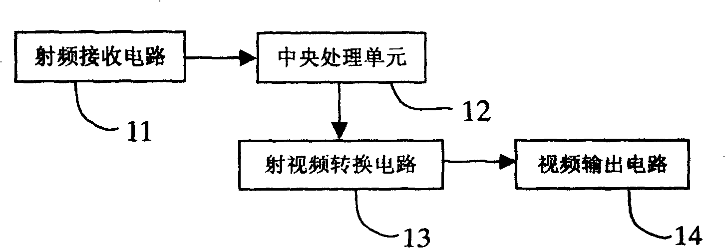
[0022] Such as figure 1 Shown is the structural block diagram of the radio-video conversion device of the present invention, the radio-frequency receiving circuit 11 receives the radio-frequency signal and outputs it to the central processing unit 12, and the central processing unit 12 outputs processing instructions to the radio-video conversion circuit 13, and the radio-video conversion circuit 13 The received signal is processed and output to the video output circuit 14, and the video output circuit 14 outputs the video signal to the user. As shown in Fig. 5, it is the concrete implementation circuit diagram of radio-video two-way conversion device of the present invention, and wherein 51 is power supply part: 220V AC power supply is output double 15V AC power through isolation transformer T1, and one road is bridge-type rectified through rectifier bridge stack RB1, capacitor C1, capacitor Filtered by C2, the voltage is stabilized to 33V by diode D2 (not shown in the figure...


PUM


Abstract

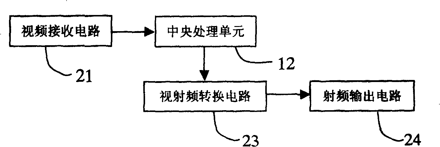
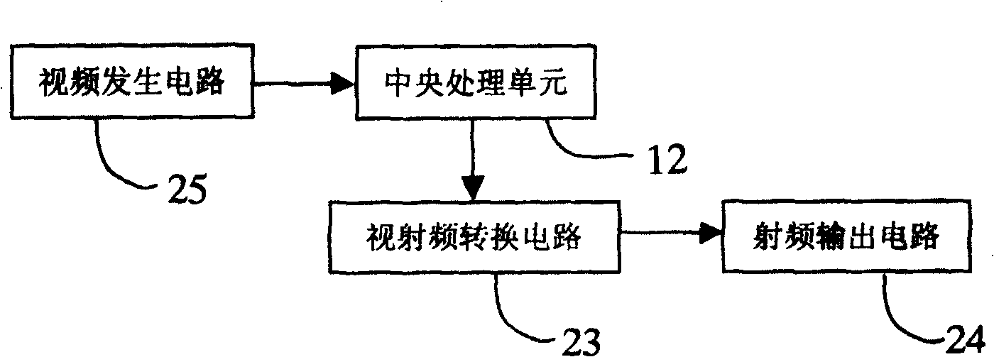
This invention discloses a RF / video conversion device including: a RF receiving circuit, a central process unit, a RF / video conversion circuit and a video output circuit, in which, the RF receiving circuit receives the RF signals to output them to the central process unit, which outputs process order to the RF / video conversion circuit, which processes the received signals and outputs them to the video output circuit to output video signals to the user. This invention also discloses a video / RF conversion device which is advantaged that the conversion of RF signal to video signals can replace the expensive signal generator in TV production, the conversion of video signals to RF signals can replace the central signal system user in TV production or is widely used in the post sale service of TV.

Description

technical field [0001] The invention relates to a conversion device, in particular to a radio-video bidirectional conversion device in the field of radio frequency and video of a television. Background technique [0002] Television sets have entered thousands of ordinary households and become the most common product in consumer electronics. The national standard system of TV radio frequency signals in my country adopts the PAL D / K system, while some video signal sources such as VCD and DVD use the PALD / K system and some use the NTSC-M system, which brings new problems to the debugging and inspection of TV manufacturers. Great inconvenience: [0003] ①Because the TV cannot enter the factory debugging mode when it is in the AV state, the station that adjusts the NTSC-M system linearity must use a signal generator (PM5518) to send out the NTSC-M system signal, which greatly increases the company’s fixed assets. input; [0004] ②Multiple AV debugging and inspection stations on...

Claims


Application Information

Patent Timeline
Patent Type & Authority Patents(China)
IPC IPC(8): H04N5/44H04N7/01
Inventor 吴伟杨军治王勇
Owner SHENZHEN SKYWORTH RGB ELECTRONICS CO LTD
Learn More