Controllable bi-circulating hot-pipe system

A double-circulation, heat pipe technology, applied in the direction of indirect heat exchangers, lighting and heating equipment, etc., can solve the problems that the use effect is not as good as the one-piece heat pipe, insufficient working fluid delivery force, uneven liquid separation, etc., to achieve convenient and continuous adjustment and control, simplify the internal structure, and solve the effect of insufficient conveying force

Inactive Publication Date: 2008-10-08
QINGDAO UNIV
View PDF6 Cites 0 Cited by
  • Summary
  • Abstract
  • Description
  • Claims
  • Application Information

AI Technical Summary

Problems solved by technology

[0004] The purpose of the present invention is to overcome the problems of insufficient working fluid delivery force, uneven liquid separation, use effect far inferior to the one-piece heat pipe and no control function of the separate heat pipe, that is, to propose a new "heat pipe system". The evaporation section and condensation section of the original "heat pipe element" are organically connected with several other necessary components to form an independent system to overcome the shortcomings of separate heat pipes
The heat pipe system forms a relatively independent working liquid cycle (small cycle in the double cycle) through the organic combination of the solution circulation pump, liquid separator, evaporator and gas-liquid separator, which solves the problem of insufficient working liquid delivery and liquid separation. The problem of unevenness; and through the control of the circulation flow, the control of the heat transfer amount of the heat pipe is realized

Method used


Image

  • Controllable bi-circulating hot-pipe system
  • Controllable bi-circulating hot-pipe system
  • Controllable bi-circulating hot-pipe system

Examples


Embodiment 1

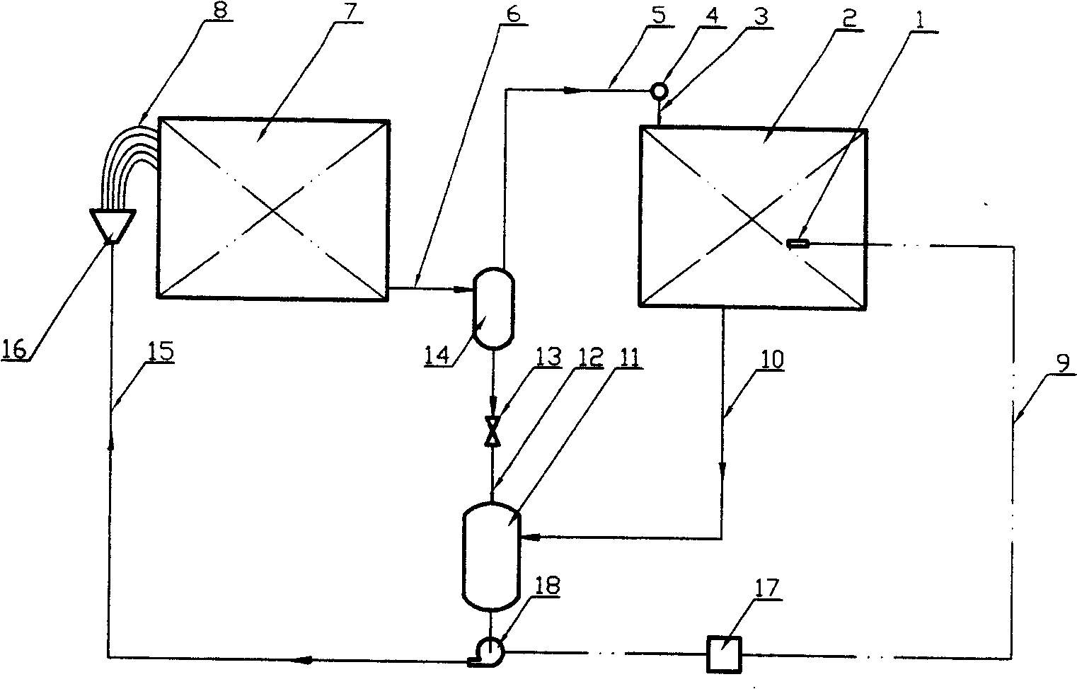
[0033] Embodiment 1: It is the structure and working process of the first kind of embodiment of the present invention, and its main components include evaporator 7 and condenser 2; The condensate liquid supply and distribution subsystem composed of the distribution tube bundle 8 of the length; the gas-liquid two-phase flow and separation subsystem composed of the two-phase flow delivery tube bundle 6 and the gas-liquid separator 14; , the gas-phase conveying and distributing subsystem composed of the gas-phase working medium main pipe 4 and the uniform gas-distributing pipe 3; it is composed of a pressure regulating valve 13, a gas-liquid separator liquid conveying pipe 12, a condenser condensate conveying pipe 10 and a liquid storage tank 11 Liquid phase collection and storage subsystem; heat exchange control subsystem composed of temperature sensor (or temperature sensing package) 1 , temperature signal transmission line 9 and temperature controller 17 . The above-mentioned ...

Embodiment 2

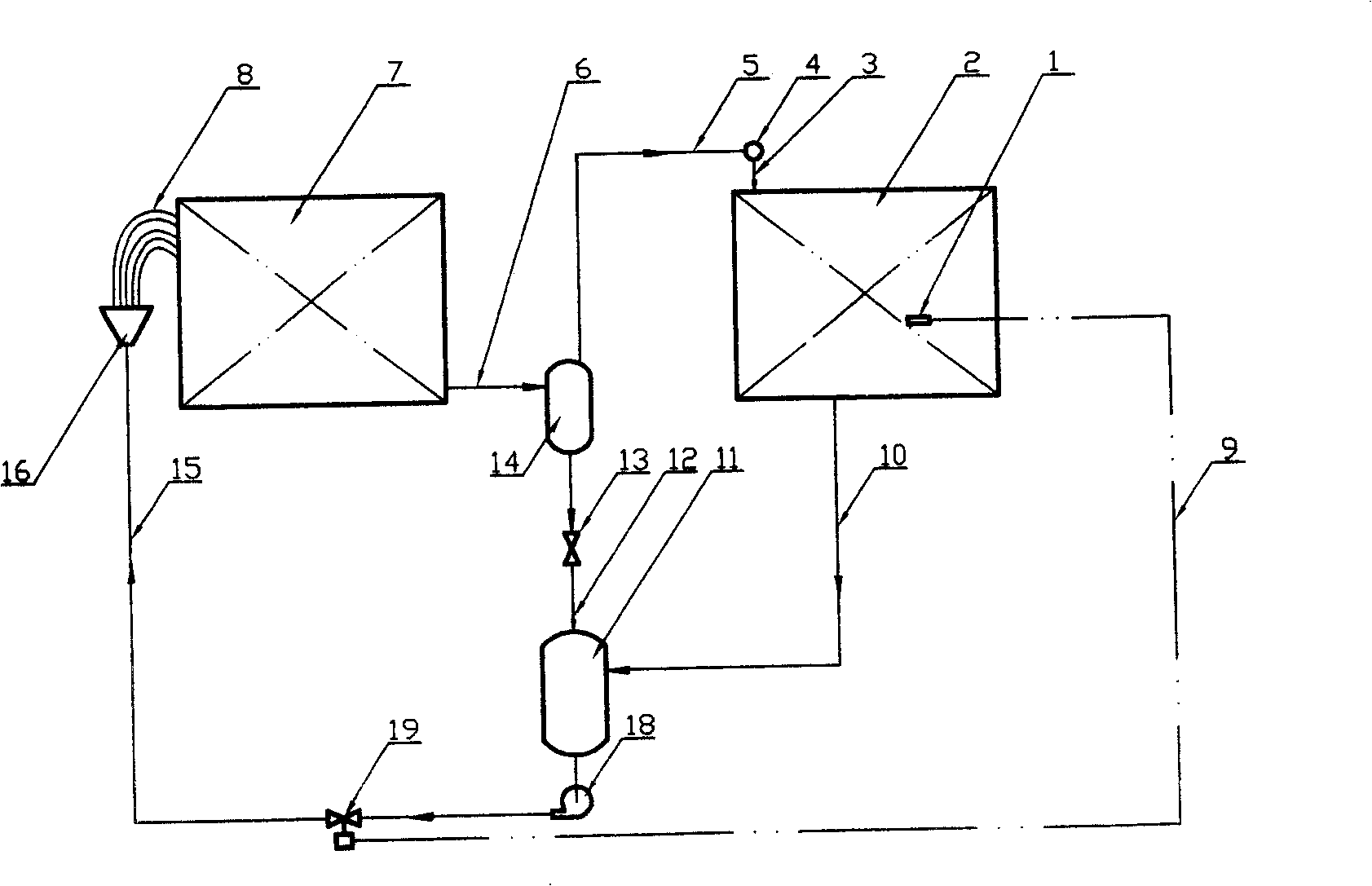
[0035] Embodiment 2: It is the structure and work flow of the second embodiment of the present invention, its evaporator 7 and condenser 2 and condensate liquid supply and distribution, gas-liquid two-phase flow and separation, gas phase transportation and distribution, and liquid phase collection The four subsystems of storage and storage are exactly the same as in Embodiment 1, but the heat exchange control subsystem is different. Embodiment 1 adopts temperature controller 17 to control the rotating speed of solution circulating pump to realize the regulation of liquid working fluid flow, present embodiment is to install temperature regulating valve 19 on circulating solution delivery pipe 15, the temperature sensing package 1, The temperature signal transmission pipe 9 directly regulates the flow rate.

[0036] The starting and running process of this embodiment is the same as that of Embodiment 1.

Embodiment 3

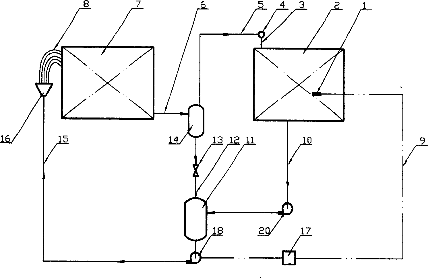
[0037] Embodiment 3: It is the structure and work flow of the third embodiment of the present invention, its evaporator 7 and condenser 2 and condensate liquid supply and distribution, gas-liquid two-phase flow and separation, gas phase transportation and distribution, and heat exchange The control of the four subsystems is exactly the same as in Example 1, but the liquid phase collection and storage are different. In Embodiment 1, the condensate of the condenser 2 flows directly into the liquid storage tank 11 by gravity, so the installation height of the liquid storage device must be lower than the lowest point of the condenser. Adding a solution pump 20 on top allows the installation height of the condenser 2 to be lower than that of the liquid receiver 11, making the installation and arrangement of the condenser more flexible.

[0038] The start-up and operation process of this embodiment is the same as that of embodiment 1. After the condensate is formed in the condenser,...


PUM


Abstract

This invention relates to a double- cycle high efficient heat pipe heat exchanging system that can control the heat exchanging quantity. There are evaporator and condenser two types of heat exchangers. The number of each type is one or several that formed by connected in parallel. This system includes: condensate supplying and distributing system; gas-liquid two phases flowing and separating system; gaseous phase transmitting and distributing system, liquid phase collecting and storing system; heat exchanging quantity controlling system. The evaporator of heat pipe, condenser, gas-liquid separator, liquid storage, solution circulating pump, liquid distributor, the connecting pipeline and related controlling parts are connected together to form the double cycles controllable heat pipe system. The solution pump, liquid distributor, evaporator and gas-liquid separator are connected together to form independent working fluid cycle, which settle the problems that working fluid carrying capacity is not enough and liquid distribution is uneven.

Description

Technical field: [0001] The invention relates to the technical field of heat pipe heat exchangers, in particular to a high-efficiency heat pipe heat exchange device with double-cycle controllable heat exchange, that is, a double-cycle controllable heat pipe system. technical background: [0002] As early as 1942, Gauler proposed the principle of heat pipes, but it has not been implemented; since Cotter first proposed a relatively complete theory of heat management in 1965, scientists from various countries have carried out theoretical research and popularization of heat pipes. As a component with high heat transfer performance, heat pipe is widely used in many fields and has achieved very good energy saving effect. In 1985, Shi Guoliang proposed the concept of "second-generation heat pipe" and applied for a national invention patent (patent number: CN 85102929). However, due to the design of the electric pump inside the heat pipe, there are great difficulties in implementat...

Claims


Application Information

Patent Timeline
Patent Type & Authority Patents(China)
IPC IPC(8): F28D15/02
Inventor 田小亮孙晖
Owner QINGDAO UNIV
Why Eureka
Try Eureka