Rotary kiln

A rotary kiln and cylinder technology, applied in the field of rotary kiln, can solve the problems of high circumferential spacing of prefabricated blocks, inapplicability, large heat dissipation loss, etc., to reduce the probability of large-area damage to the furnace lining, strengthen the overall sealing performance, economical Benefit-enhancing effect

Active Publication Date: 2008-10-22
ZHONGYE-CHANGTIAN INT ENG CO LTD
View PDF7 Cites 0 Cited by
  • Summary
  • Abstract
  • Description
  • Claims
  • Application Information

AI Technical Summary

Problems solved by technology

This method has the following disadvantages: 1) the wedge-shaped brick has a small size and head width difference, and the brick-to-brick combination is poor, and the brick is easy to fall off; 2) the masonry has strict requirements on the tolerance of the shape and size of the brick; 3) the construction is difficult with small brick joints, and the construction period Long; 4) With the extension of the running time, the wear of the bricks reaches a certain level, and it is easy to cause brick falling and collapse accidents
This method also has the following disadvantages: 1) The prefabricated anchor brick is welded together with the kiln shell by the outer part of the inner reinforcement. Large, the temperature of the cylinder increases and the heat dissipation loss is large
2) The thermal expansion of the internal reinforcement in the prefabricated anchor brick is inconsistent with the expansion coefficient of the refractory material, and the expansion of the reinforcement will cause damage to the prefabricated block and affect the life of the prefabricated block; 3) The production cycle is long, the production process is relatively complicated, and the production cost is high
In the rotary kiln disclosed in this patent document 1, "one end of the anchor is provided with a hook", therefore, the number of anchors required to fix the prefabricated block is large, the material consumption is large, the welding cost of the anchor is high, and the construction is complicated
In addition, the rotary kiln disclosed in this patent document is composed of prefabricated blocks fixed by anchors within a circle. This structure will make it very difficult to weld the anchors when installing the last prefabricated block, and requires kiln straightness and prefabricated block accuracy. , Prefabricated block circumferential spacing accuracy is very high, the construction is difficult, and for rotary kilns with unequal diameters, this structure cannot be applied

Method used


Image

  • Rotary kiln
  • Rotary kiln
  • Rotary kiln

Examples


Embodiment Construction

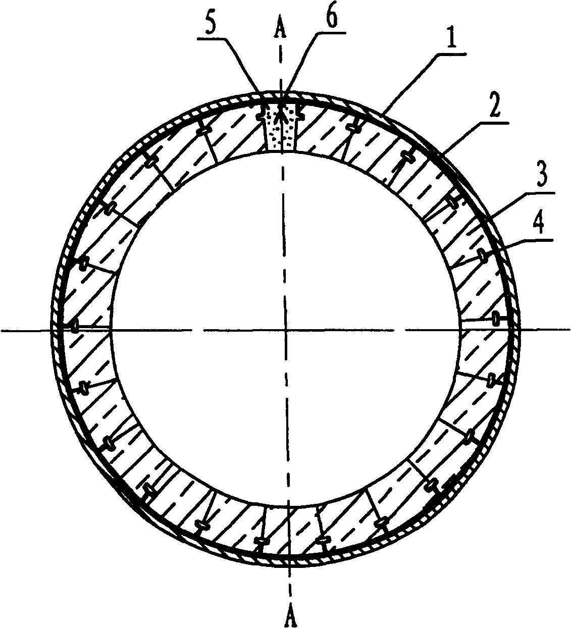
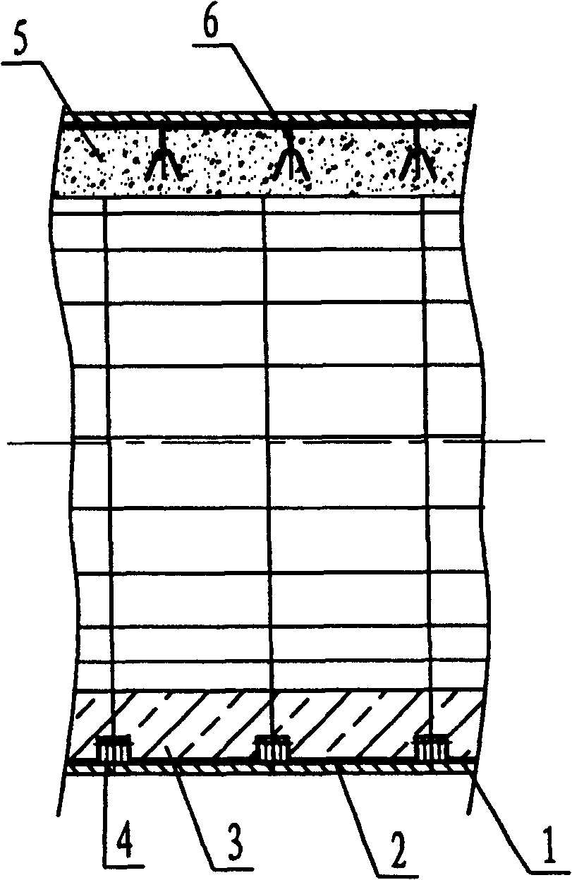
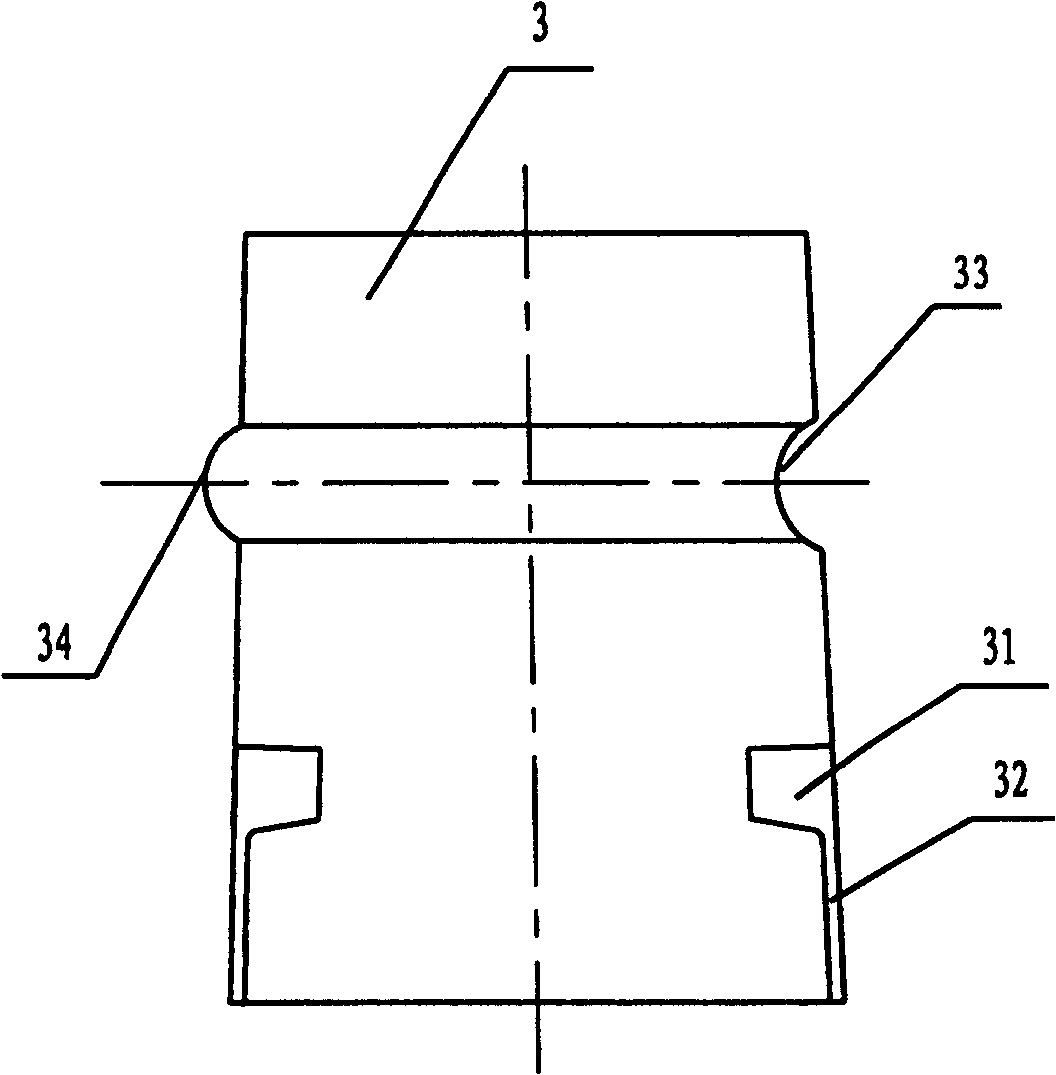
[0015] like figure 1 , 2 As shown, the rotary kiln of the present invention includes a cylinder body 1, a thermal insulation layer 2 and a furnace lining. The furnace lining is fixed on the cylinder body 1 by refractory bricks 3 through anchors 4, and the installation position on the refractory bricks 3 is in line with the axis of the rotary kiln cylinder body. There are hook holes 31 and hook concave surfaces 32 respectively on the two joint surfaces with the same direction (see image 3 ). see Figure 5 , 6 , 7, one end of the anchor 4 is provided with two hooks 41, which are respectively hooked into the hook holes 31 of the aforementioned two adjacent refractory bricks, and the other end of the anchor 4 is a welded body 42, which is welded on the cylinder 1, on a circle The interface of the inner refractory brick 3 is connected with castable 5 . Anchor nails 6 welded to the cylinder body 1 are arranged in the pouring material 5 .

[0016] like image 3 , 4 As shown,...


PUM


Abstract

The present invention provides one kind of rotary kiln with short lining producing period, simple production process, easy construction and maintenance, long service life and high heat efficiency. The rotary kiln includes a cylinder, a heat isolating layer and a furnace lining. The furnace lining consists of refractory bricks fixed with anchoring parts onto the cylinder, and the anchoring part has two hooks inserted into the holes in the refractory bricks in one end and the other end welded to the cylinder. The seams between refractory bricks are sealed with deposited material or interface bricks.

Description

technical field [0001] The invention belongs to a rotary kiln, specifically relates to the improvement of the furnace lining structure thereof, and is mainly applicable to roasting equipment such as metallurgy, chemical industry and building materials. Background technique [0002] There are basically two commonly used methods for building the inner lining of the existing rotary kiln. One is to use refractory bricks to build with staggered joints or circular joints. This method has the following disadvantages: 1) the wedge-shaped brick has a small size and head width difference, and the brick-to-brick combination is poor, and the brick is easy to fall off; 2) the masonry has strict requirements on the tolerance of the shape and size of the brick; 3) the construction is difficult with small brick joints, and the construction period Long; 4) With the prolongation of the running time, the wear of bricks reaches a certain level, and accidents of falling bricks and subsidence are...

Claims


Application Information

Patent Timeline
Patent Type & Authority Patents(China)
IPC IPC(8): F27B7/02F27B7/22F27D1/04
CPCF27D1/14F27D1/045F27D1/10F27B7/28
Inventor 贺新华王赛辉李文辉丁智清宁德乙沈维民朱飞周丹
Owner ZHONGYE-CHANGTIAN INT ENG CO LTD
Why Eureka
Try Eureka