An engine with a plurality of operating modes including operation by compressed air
An operating mode, engine technology, used in variable displacement engines, reciprocating piston engines, engines with one-way flow principles, etc.
- Summary
- Abstract
- Description
- Claims
- Application Information
AI Technical Summary
Problems solved by technology
Method used
Image

Examples
Embodiment Construction
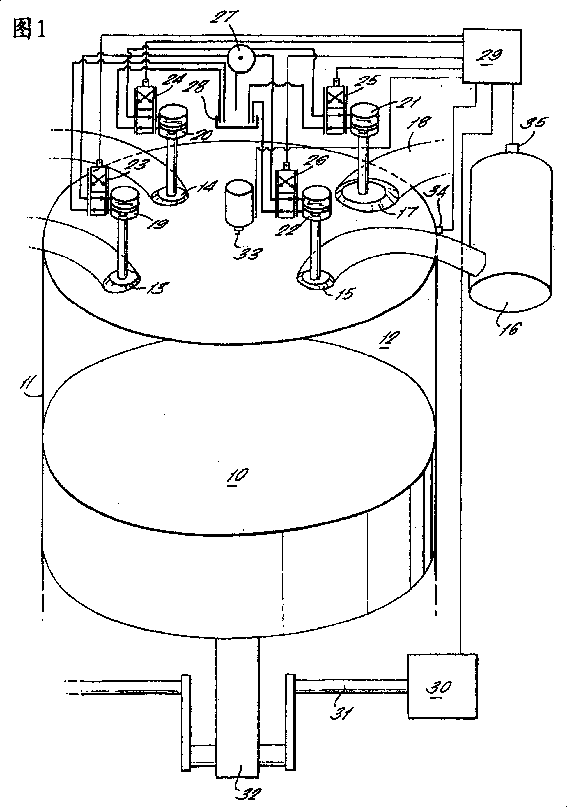
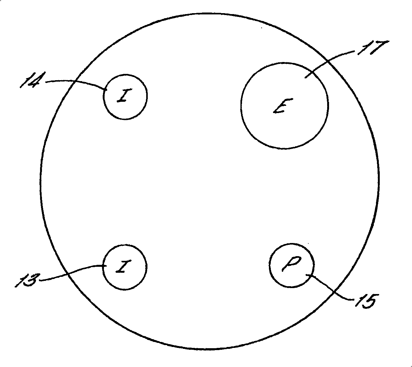
[0013] In FIG. 1 , a piston 10 is shown reciprocating inside a cylinder 11 and with which a variable volume combustion chamber 12 is defined. Two intake valves 13 and 14 control the flow of charge air to the combustion chamber 12 . The gas flow control valve 15 controls the flow of pressurized air to and from the pressure vessel 16, as will be described later. An exhaust valve 17 controls the flow of burned gases out of the combustion chamber from an exhaust passage 18 which vents the exhaust gases to the atmosphere. Injector 33 injects fuel into the combustion chamber and also includes the spark plug.
[0014] Each of the four valves 13, 14, 15 and 17 is connected to each of the four hydraulic actuators 19, 20, 21 and 22 which are connected to each of the four electrically operated control valves 23 associated therewith. , Under the control of 24, 25, 26 the valves 13, 14, 15 and 17 are opened and closed. Each control valve 23, 24, 25, 26 is also connected to a source 27 o...
PUM
 Abstract
Description
Claims
Application Information
 - R&D
- Intellectual Property
- Life Sciences
- Materials
- Tech Scout
- Unparalleled Data Quality
- Higher Quality Content
- 60% Fewer Hallucinations
Browse by: Latest US Patents, China's latest patents, Technical Efficacy Thesaurus, Application Domain, Technology Topic, Popular Technical Reports.
© 2025 PatSnap. All rights reserved.Legal|Privacy policy|Modern Slavery Act Transparency Statement|Sitemap|About US| Contact US: help@patsnap.com