High energy high efficiency direct current ignition device of motorcycle

A technology for ignition devices and motorcycles, applied in induction energy storage devices, other devices, engine ignition, etc., can solve problems such as short spark duration, restricting engine performance, and limiting ignition system power.

Inactive Publication Date: 2008-12-10
白承基 +1
View PDF6 Cites 0 Cited by
  • Summary
  • Abstract
  • Description
  • Claims
  • Application Information

AI Technical Summary

Problems solved by technology

[0003] Compared with the inductive discharge ignition system, the CDI ignition system has the advantage of fast ignition, but the biggest disadvantage of this system is that the spark duration is very short (about a few hundred nanoseconds), and the electric energy provided by the motorcycle power supply to the ignition system Restricted, the mixed gas cannot be fully burned, which restricts the performance of the engine and correspondingly increases the emission of pollutants

Method used


Image

  • High energy high efficiency direct current ignition device of motorcycle
  • High energy high efficiency direct current ignition device of motorcycle
  • High energy high efficiency direct current ignition device of motorcycle

Examples


Embodiment Construction

[0013] Describe the structure and working principle of the motorcycle DC ignition device of the present invention below in conjunction with accompanying drawing.

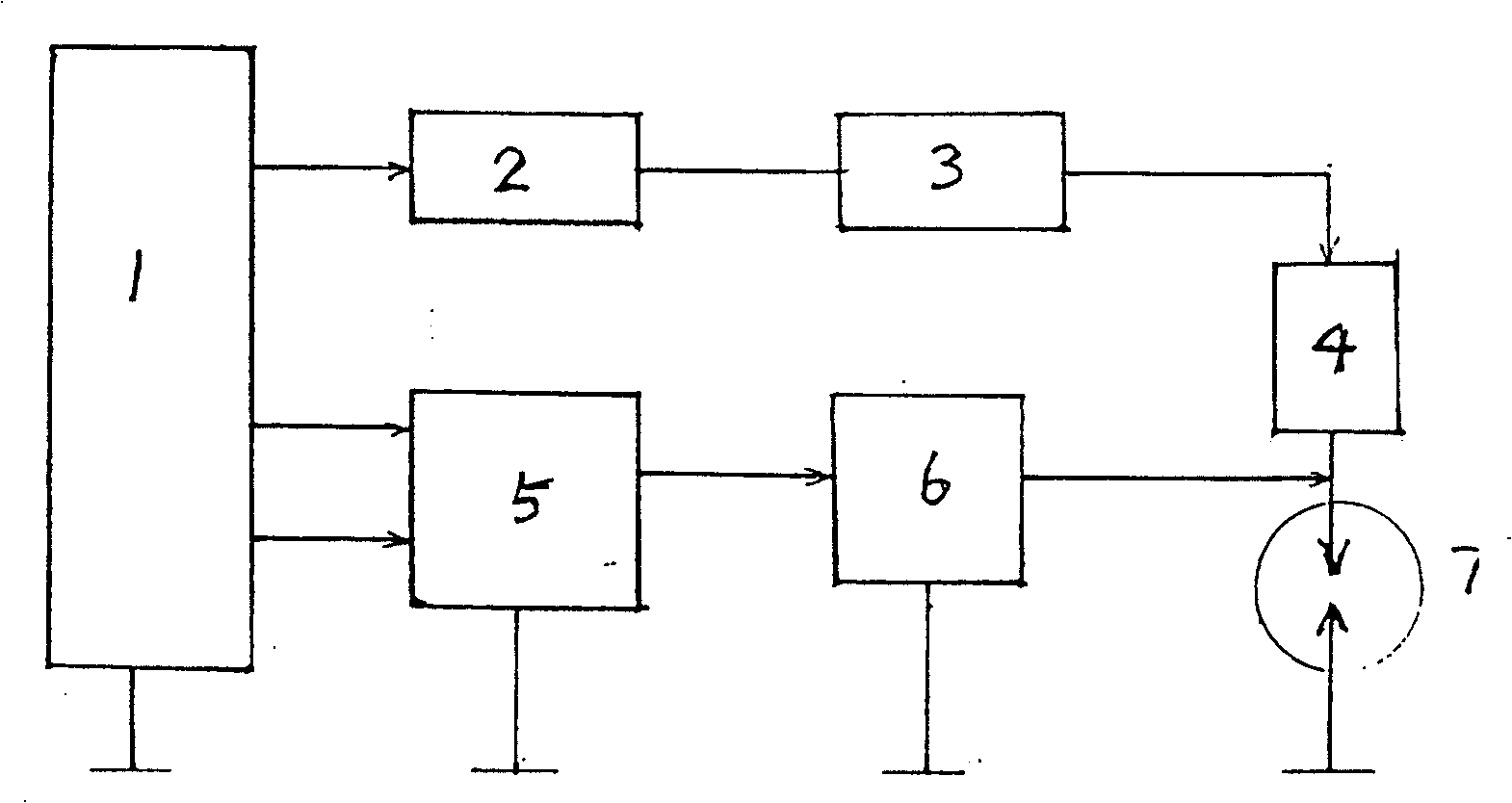
[0014] Such as figure 2 As shown, the motorcycle DC ignition device of the present invention includes a magneto 1 , a CDI ignition system 5 , an ignition coil 6 , a spark plug 7 , a DC voltage booster 2 , an isolation system 3 , and a delayer 4 . Among them, one winding of the magneto is connected to the DC voltage booster 2, the output of the DC voltage booster 2 is connected to the spark plug 7 through the isolation system 3 and the delayer 4, and the other two windings of the magneto are connected to the CDI system 5, and the CDI The output of the system 5 is connected to the primary of the ignition coil 6, and the secondary of the ignition coil 6 is connected to the spark plug.

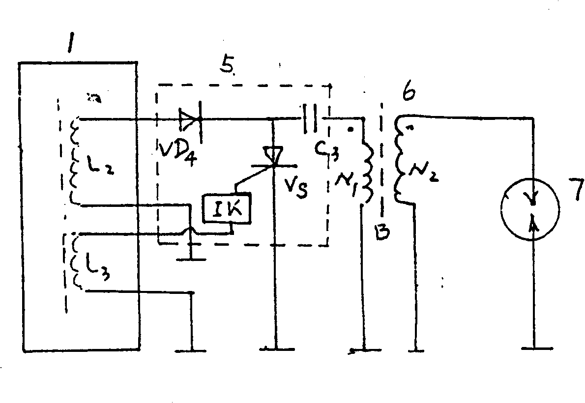
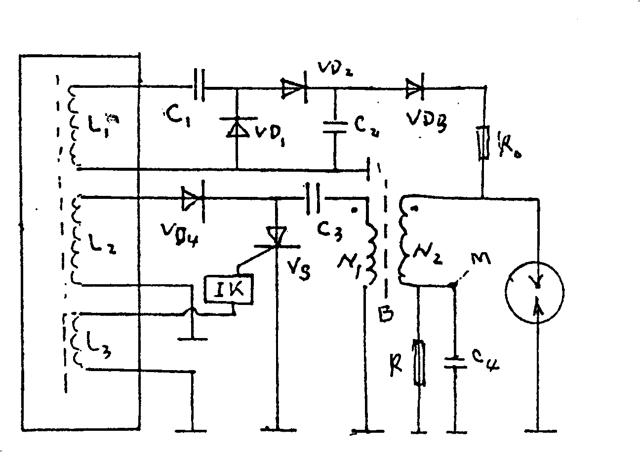
[0015] Combine below image 3 The electrical schematic diagram of the detailed description of the working process of the present in...


PUM


Abstract

This invention relates to motorcycle direct current portfire with high efficiency, which belongs to motorcycle portfire technique and adds one magnetic machine coil on the base of motorcycle original capacity portfire system. The portfire coil second adopts floating earth method and realizes the aim by multiplying the coil through high reverse diode and connecting the piston electrode.

Description

Technical field [0001] The invention belongs to the field of fuel motorcycle ignition devices. Background technique [0002] Contemporary motorcycles all use capacitor discharge ignition system, which is called CDI ignition system. The following introduces the working principle of the CDI ignition system. figure 1 A conventional motorcycle ignition device is shown, wherein the ignition device includes a magneto 1, a CDI ignition system 5, an ignition coil 6, a spark plug 7, and a magneto winding L 2 , Diode VD 4 , SCR V S , trigger switch IK, capacitor C 3 , ignition coil 6 and spark plug 7 constitute a standard capacitive discharge ignition system, at this time, L 2 The output voltage via VD 4 to C 3 Charge. Under the triggering action of the trigger switch IK, the one-way thyristor V S conduction, C 3 Energy through the ignition coil primary N 1 release, the ignition coil secondary N 2 An ignition high voltage is generated in the middle, the spark plug is broke...

Claims


Application Information

Patent Timeline
Patent Type & Authority Patents(China)
IPC IPC(8): F02P3/04F02P3/00
Inventor 白承基程凤岐
Owner 白承基
Why Eureka
Try Eureka