Air-assisted type spraying machine controller based on microcomputer

A technology of control device and sprayer, which is applied in the direction of injection device, computer control, emergency protection device with automatic disconnection, etc. It can solve the problems of nozzle blockage, coil voltage instability, fan frequent start and so on, and achieve the effect of reducing noise

Inactive Publication Date: 2008-12-17
SOUTH CHINA AGRI UNIV
View PDF5 Cites 0 Cited by
  • Summary
  • Abstract
  • Description
  • Claims
  • Application Information

AI Technical Summary

Problems solved by technology

During the operation of the sprayer, the operator can change the working state of the sprayer through the remote control button. During this period, the operator cannot leave the control box of the sprayer
In the traditional control device, the Y-Δ starting method is usually used to start the fan with large power. However, in the occasions where self-generated power is required, such as the vehicle-mounted air-supply sprayer, its products are limited by cost or volume, and it is impossible to use high-power, belt-driven fans. A large generator set with a strong load capacity, which leads to large fluctuations in the output voltage of the generator set during the start-up process of the fan, resulting in unstable coil voltage of the AC contactor, unable to firmly pull in each contact, causing the fan to be damaged in a short period of time. The phenomenon of frequent starting, and because of the high-voltage arc generated at the moment of contact closure, it is easy to shorten the life of the contact
In addition, since the start and stop of the fan and the start and stop of the water pump are controlled separately, it is easy to start the water pump first and then the fan, resulting in clogging of the nozzle, and it is difficult to grasp the time interval between starting the fan and the water pump, and it is impossible to guarantee that the fan is completely running. When the water pump is started again, the operator cannot stay away from the control box and the spraying site during the operation. The mist liquid falling from the crops will have a great impact on the health of the operator, and in severe cases, it will cause pesticide poisoning.

Method used


Image

  • Air-assisted type spraying machine controller based on microcomputer
  • Air-assisted type spraying machine controller based on microcomputer
  • Air-assisted type spraying machine controller based on microcomputer

Examples


Embodiment 1

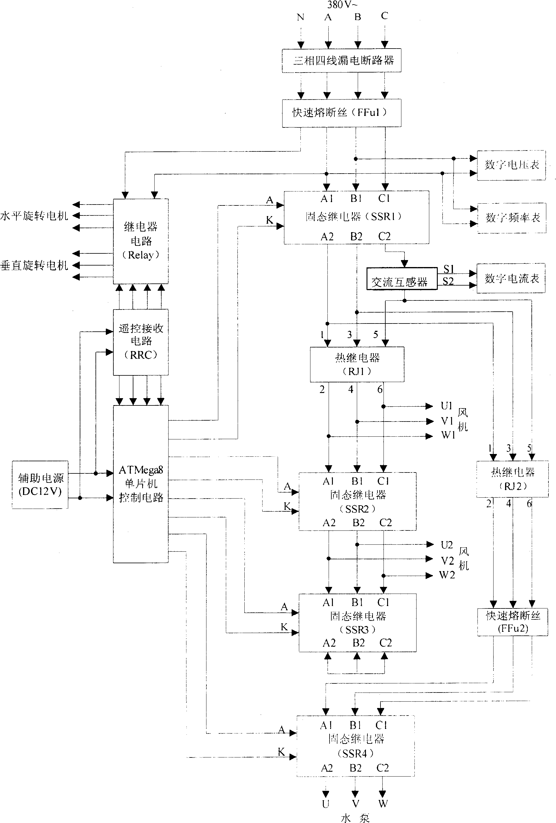
[0032] Such as figure 1As shown, the microcomputer-based air-supply sprayer control device is composed of ATMega8 single-chip control circuit, remote control receiving circuit (RRC), relay circuit (Relay), three-phase four-wire leakage circuit breaker, the first fast fuse FFu1, the second Two fast fuse FFu2, the first solid state relay SSR1, the second solid state relay SSR2, the third solid state relay SSR3, the fourth solid state relay SSR4, the first thermal relay RJ1, the second thermal relay RJ2, 12V DC auxiliary power supply and digital voltmeter , digital frequency meter, digital ammeter and AC transformer.

[0033] The MCU is connected to the auxiliary power supply, the remote control receiving circuit (RRC) and the control terminals of the first solid state relay SSR1, the second solid state relay SSR2, the third solid state relay SSR3, and the fourth solid state relay SSR4 respectively, and the three phase lines A of the three-phase power supply , B, C and neutral l...


PUM


Abstract

The air assistant sprayer comprises single chip machine, remote control emitting circuit, remote receiving circuit, three phase four wire electricity leakage circuit and solid relay. It's working status can be controlled through the press button wire control of the control panel or the remote controller within the range of 500m, with each working parameter of the sprayer displayed on the meter, with the operator can control the working process away from the sprayer or the driver's cabin, with reduced noise, electromagnetic wave, shattering dispersed soup to the health of the operator. The assistant electricity power of the single chip machine getting from the 12V DC battery, getting rid of the potential threat of the high voltage to the operator, ensuring the stable running of the control circuit.

Description

technical field [0001] The invention relates to a control device for an air-supply sprayer, in particular to a control device for an air-supply sprayer based on a microcomputer. Background technique [0002] The traditional air-driven sprayer control device uses an AC contactor with a coil voltage of 380V, a time relay whose time cannot be continuously adjusted to complete the control and conversion of the working status of the fan and water pump. The start and stop of the fan and the start and stop of the water pump are completed by wire control with four separate buttons. During the operation of the sprayer, the operator changes the working state of the sprayer through the wire control button, during which the operator cannot leave the control box of the sprayer. In the traditional control device, the Y-Δ starting method is usually used to start the fan with large power. However, in the occasions where self-generated power is required, such as the vehicle-mounted air-supp...

Claims


Application Information

Patent Timeline
Patent Type & Authority Patents(China)
IPC IPC(8): G05B19/042B05B15/00H02H3/00
Inventor 洪添胜梁华新孙道宗宋淑然李震朱余清陆永超
Owner SOUTH CHINA AGRI UNIV
Why Eureka
Try Eureka