Eureka AIR delivers breakthrough ideas for toughest innovation challenges, trusted by R&D personnel around the world.

Optical recording medium, method and apparatus for recording data thereon

A technology for optical recording media and data recording, applied in optical recording/reproducing/erasing methods, optical recording systems, optical erasing systems, etc., and can solve the problems of reduced, severe, and reduced reproduction characteristics of recording/reproducing signals

Inactive Publication Date: 2008-12-17
SAMSUNG ELECTRONICS CO LTD
View PDF6 Cites 0 Cited by
  • Summary
  • Abstract
  • Description
  • Claims
  • Application Information

AI Technical Summary

Problems solved by technology

As a result, the distortion of the shape of the mark becomes more severe
[0007] In other words, since erasing is performed using erasing power having a predetermined DC level during data recording, recording / noise such as a carrier-to-noise (C / N) signal is caused due to thermal interference between a plurality of recording pulses. The reproduction signal is reduced, and marks are formed incompletely and then crystallized, causing a reduction in reproduction characteristics
Specifically, when data recording is performed at high speed to increase the data transfer speed, the distortion of the recording / reproducing signal significantly increases

Method used


Image

  • Optical recording medium, method and apparatus for recording data thereon
  • Optical recording medium, method and apparatus for recording data thereon
  • Optical recording medium, method and apparatus for recording data thereon

Examples


Embodiment Construction

[0033] Embodiments of the present invention will now be described in detail, examples of which are illustrated in the accompanying drawings, wherein like reference numerals refer to like parts throughout. The embodiments are described below in order to explain the present invention by referring to the figures.

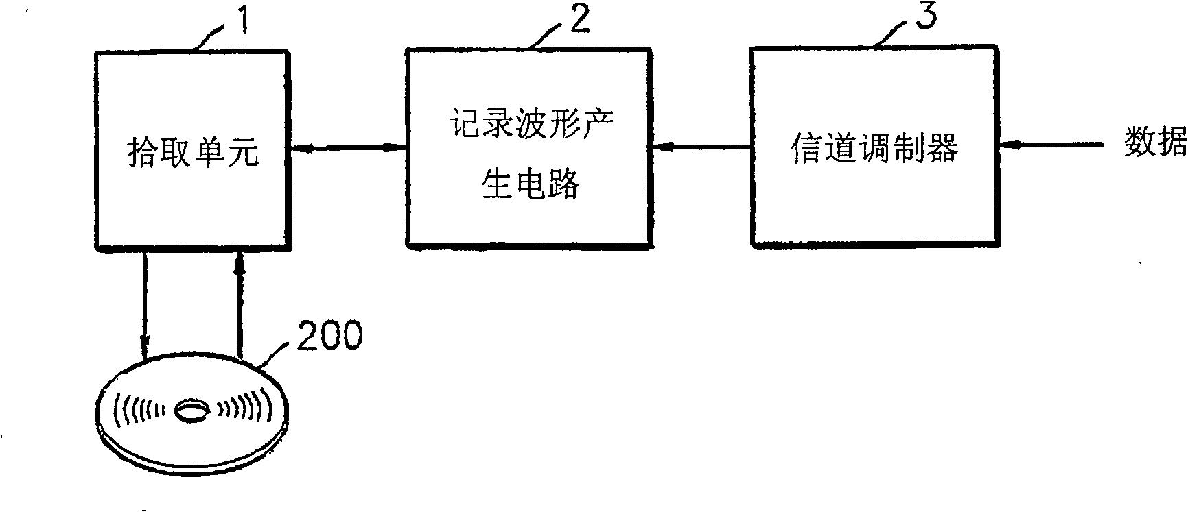
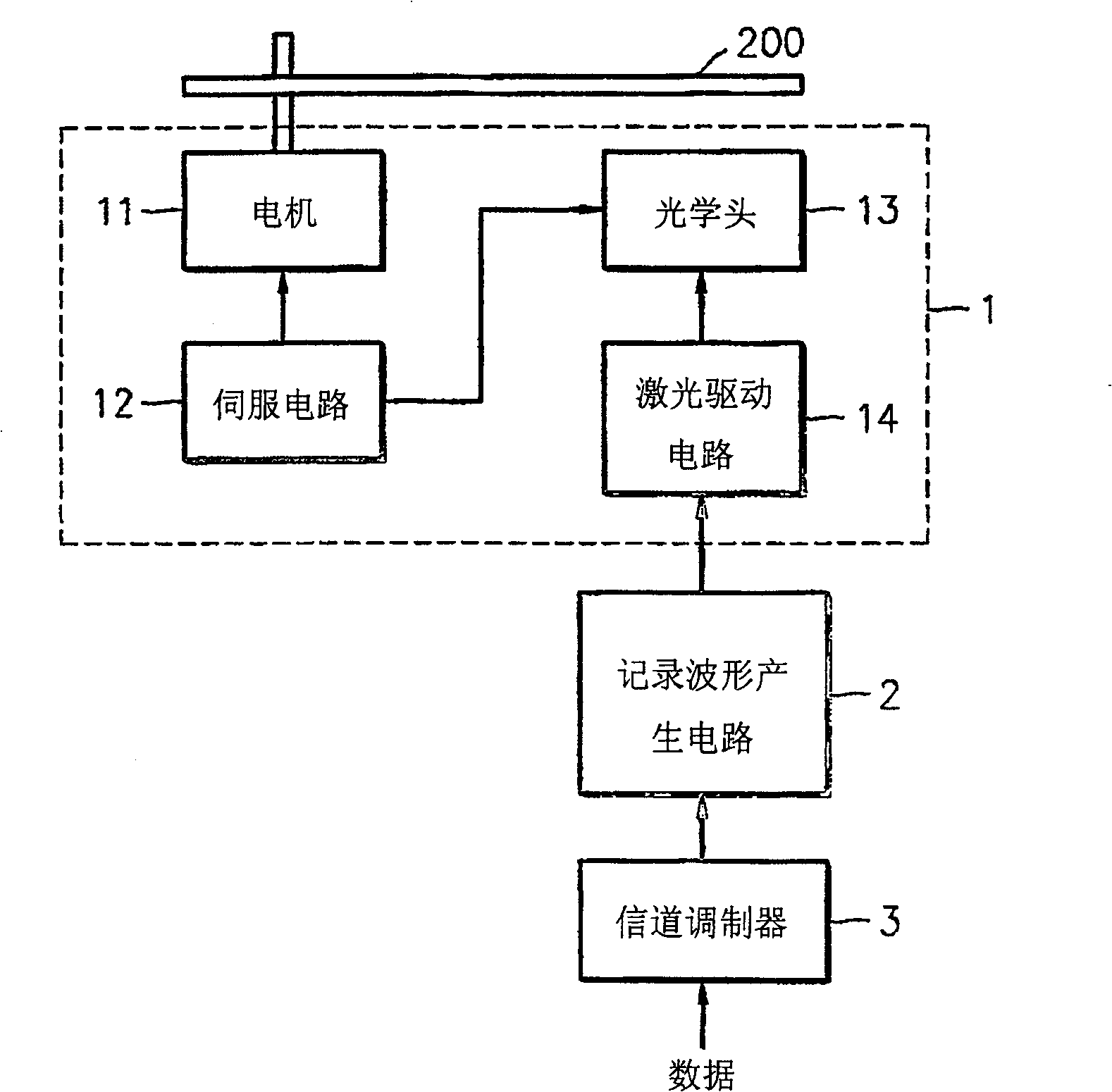
[0034] figure 2 is a block diagram of an apparatus for recording data according to an embodiment of the present invention.

[0035] refer to figure 2 , an apparatus for recording data by forming marks or spaces in an optical recording medium 200 and includes a pickup unit 1 , a recording waveform generating circuit 2 and a channel modulator 3 .

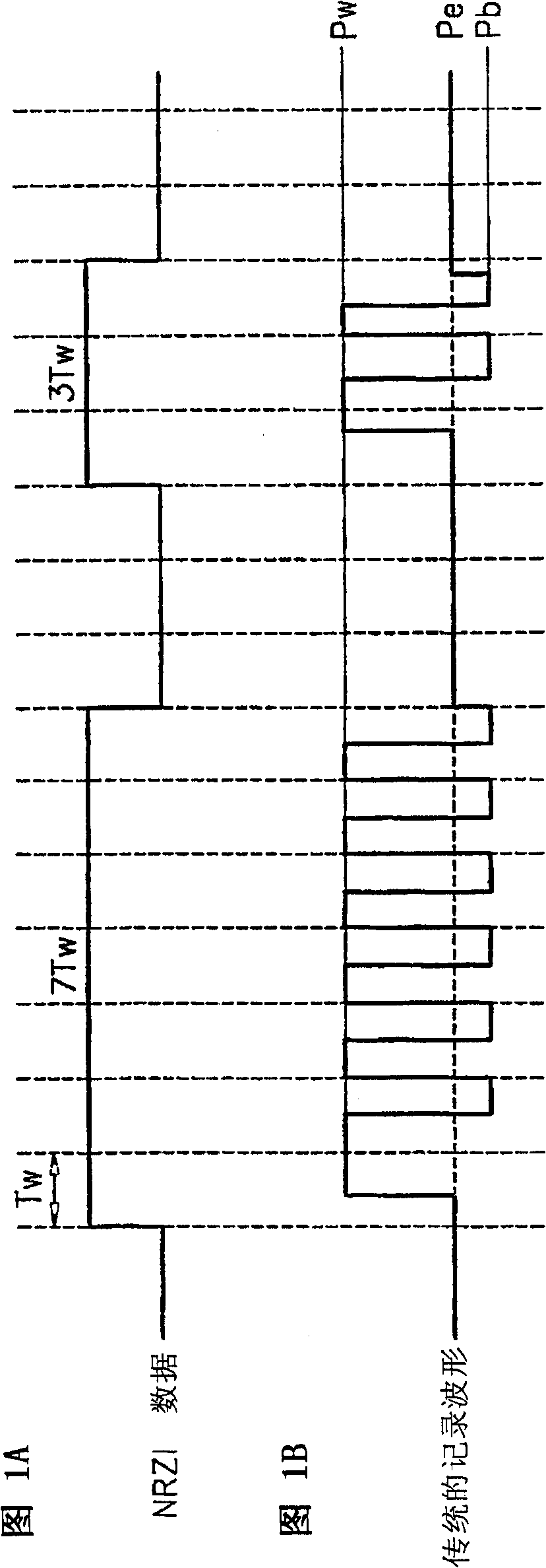
[0036] The channel modulator 3 modulates data input from the outside into a channel bit stream. The recording waveform generation circuit 2 receives the channel bit stream and generates a recording waveform. The recording waveforms generated according to the present invention include a recording mode for being recorded at a ...


PUM


Abstract

PURPOSE: A device for recording data on an optical recording medium is provided to set a low level of a recording power of a recording pattern to be higher than a bias power level, in order to sufficiently absorb heat on a recording film even when data is recorded at high speed, thereby improving edge characteristics of a recording mark. CONSTITUTION: A pickup unit(1) comprises as follows. A motor(11) rotates an optical disk(200). An optical head(13) irradiates a laser light on the optical disk(200), or receives the laser light reflected from the optical disk(200). A servo circuit(12) servos the motor(11) and the optical head(13). A laser driving circuit(14) drives a laser installed on the optical head(13). A channel modulator(3) modulates inputted data into channel bit strings, and outputs NRZI(Non Return to Zero Inverted) data. A recording waveform generation circuit(2) generates a recording waveform for recording the NRZI data, and supplies the recording waveform to the laser driving circuit(14). The laser driving circuit(14) controls the laser by using the recording waveform, and forms a mark or a space on the optical disk(200).

Description

technical field [0001] The present invention relates to recording data on an optical recording medium, and more particularly to an optical recording medium storing information related to a write strategy for high-speed recording, and an optical recording medium for recording data on the optical recording medium. Methods and apparatus on the medium. Background technique [0002] When data is recorded on the optical recording medium, marks are formed in the tracks of the optical disc. In read-only discs such as compact disc read-only memory (CD-ROM) and digital versatile disc-read-only memory (DVD-ROM), marks are formed as pits. In recordable discs such as Compact Disc - Recordable / Rewritable (CD-R / RW) and Digital Versatile Disc - Recordable / Rewritable / Random Access Memory (DVD-R / RW / RAM), The recording layer is coated with a phase change layer that enters a crystalline or amorphous state in response to temperature changes, and marks are formed from changes in the phase of th...

Claims


Application Information

Patent Timeline
Patent Type & Authority Patents(China)
IPC IPC(8): G11B7/004
CPCG11B7/00456G11B7/0055
Inventor 李坰根安龙津黄郁渊尹斗燮朴仁植金成洙
Owner SAMSUNG ELECTRONICS CO LTD
Why Eureka
Eureka Blog
Learn More