Ignition device for IC engine
A technology of ignition device and sealing device, which is applied in the direction of engine ignition, induction energy storage device, spark ignition controller, etc., can solve the problems of difficult assembly process, ignition coil retention, disadvantage, etc.
- Summary
- Abstract
- Description
- Claims
- Application Information
AI Technical Summary
Problems solved by technology
Method used
Image
Examples
no. 1 approach
[0069] (another modification of the first embodiment)
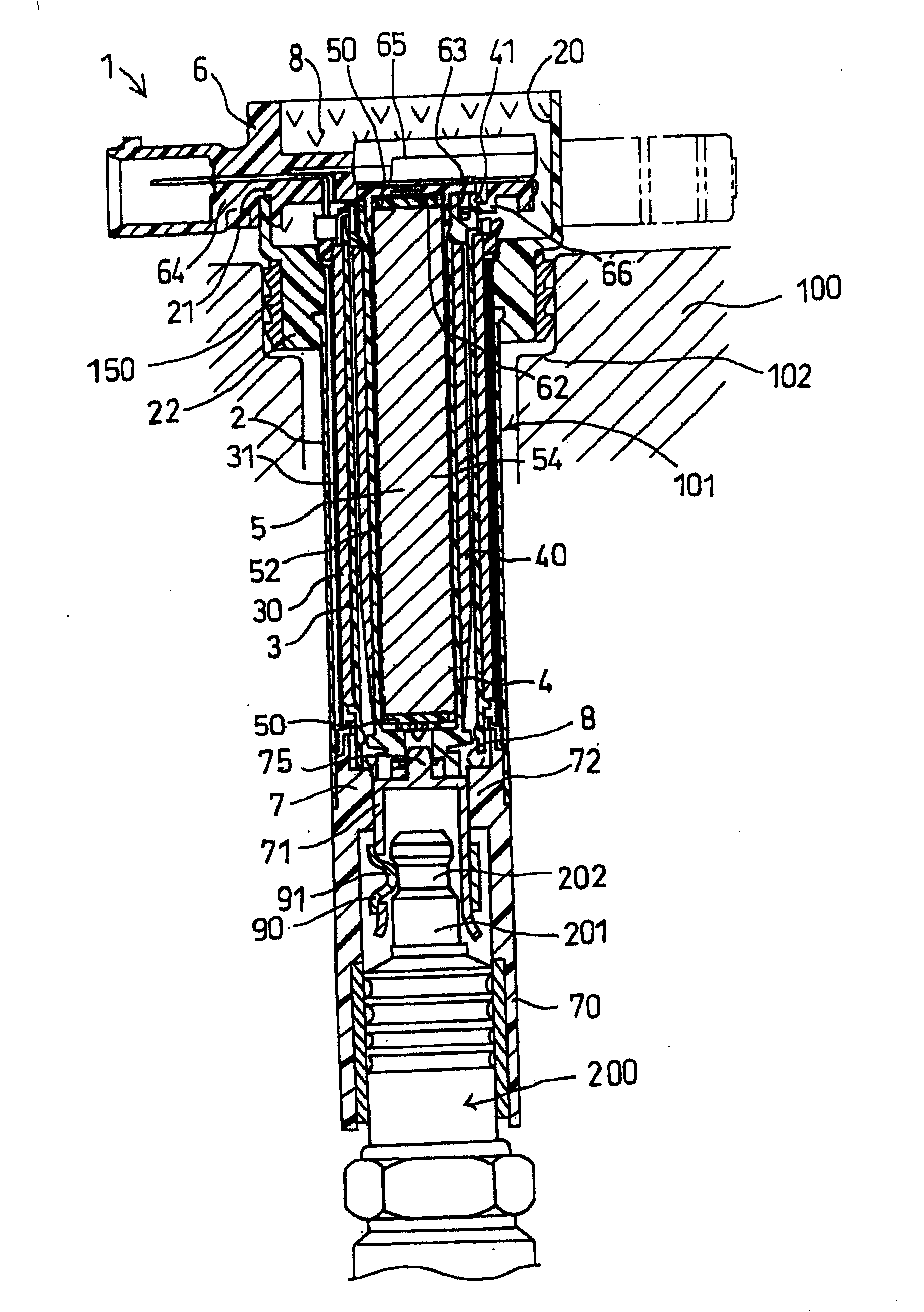
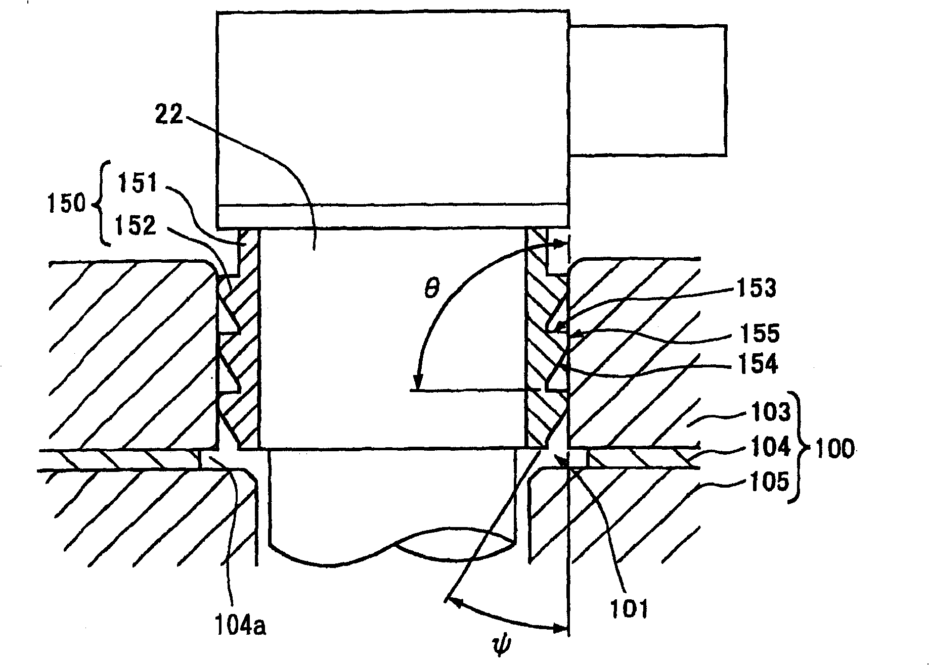
[0070] Although not shown in the figures, any other modification is possible. For example, figure 2 The sealing device 150 in the illustrated embodiment can be broken down into three separate elements, each having a sealing protrusion 152 thereon. And three annular grooves can be made on the outer peripheral surface of the second enlarged part 22 of the coil housing 1, so that each sealing element 150 will be held by these annular grooves. As a result, the same effects as those of the first embodiment can be obtained.
no. 2 approach
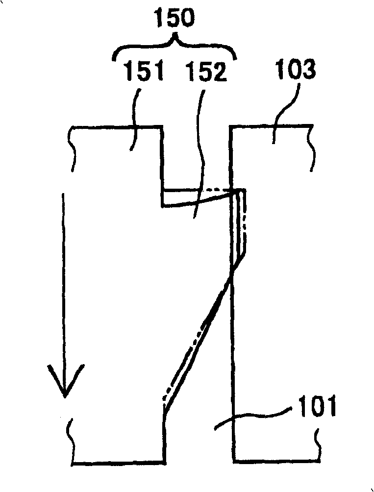
[0072] The following will refer to Figure 5 The second embodiment is introduced with FIG. 6 . Figure 6A shows the situation when the ignition coil 1 is being inserted into the plug hole 101, Figure 6B It shows the situation when the ignition coil 1 is being pulled out from the plug hole 101, wherein, the two-dot dash line represents the state of the sealing device 150 before being inserted into the plug hole 101, and the solid line represents the state of the sealing device before being inserted into the plug hole 101. The state after plug hole 101.
[0073] follow with figure 2 In the same manner as the embodiment, the sealing device 150 in this embodiment includes a cylindrical sealing body 156 and a plurality of sealing protrusions 152 .
[0074] On the outer peripheral surface of the second enlarged portion 22, a plurality (three) of annular casing protrusions 23 are formed in the longitudinal direction. The housing projection 23 is also made asymmetric with respec...
no. 3 approach
[0085] The following will refer to Figure 9 The third embodiment is introduced, which is the same as figure 2 The illustrated embodiment is similar.
[0086] like Figure 9 As shown, a step portion 106 is made on the first cover body 103, so that the diameter of the plug hole 101 formed by the bottom (large diameter portion) of the first cover body 103 is greater than that of the first cover body 103 top (small diameter portion). diameter. The mold for manufacturing the first cover 103 is composed of at least two separate molds, wherein the boundary line of these separate molds corresponds to the stepped portion 106 . Therefore, it is not necessary to provide a corresponding stepped portion on the mold.
[0087] One of the protrusions ( 160 ) of the sealing protrusions 152 is located at the lowermost position, which is made such that the diameter of the outer peripheral end of the lowermost protrusion 160 is slightly larger than the diameters of the other two protrusions...
PUM
 Abstract
Description
Claims
Application Information
 - R&D Engineer
- R&D Manager
- IP Professional
- Industry Leading Data Capabilities
- Powerful AI technology
- Patent DNA Extraction
Browse by: Latest US Patents, China's latest patents, Technical Efficacy Thesaurus, Application Domain, Technology Topic, Popular Technical Reports.
© 2024 PatSnap. All rights reserved.Legal|Privacy policy|Modern Slavery Act Transparency Statement|Sitemap|About US| Contact US: help@patsnap.com


