
10/350 shock current system for air or vacuum CROWBAR switch

A technology of inrush current and direct lightning strike, applied in the field of overvoltage protector impulse system, can solve the problems of air spark switch erosion, CROWBAR switch cumbersome, difficult adjustment and coordination, etc., to ensure reliability and stability, steep pulse rise time, The effect of large flow capacity

Inactive Publication Date: 2009-01-21
XI AN JIAOTONG UNIV
View PDF2 Cites 1 Cited by
  • Summary
  • Abstract
  • Description
  • Claims
  • Application Information

AI Technical Summary

Problems solved by technology

Such a large impact energy will cause the following problems: First, the energy of thousands of kilojoules needs hundreds or even thousands of μF capacitors to store, the impact current generator is very large, and the safety and reliability of high voltage operation On the other hand, thousands of kilojoules of energy will be released on the discharge switch, which will seriously corrode the commonly used air spark switch, and the huge energy release will cause electromagnetic and noise pollution to the operating environment
[0007] It can be seen that the I(B) gap type 10 / 350μs impulse current test system has very strict requirements on the short-circuit CROWBAR switch, otherwise, the stability and reliability of the short-circuit CROWBAR switch and the impulse current test system cannot be guaranteed at all.
[0008] In addition to being bulky, the CROWBAR switch in the I(B) gap type 10 / 350μs impulse current test system developed by HAEFELY company has a very obvious shortcoming that the three electrodes of the short-circuit CROWBAR switch need to adjust the gap distance according to the test conditions, and the adjustment It is very difficult to cooperate, and it is also affected by air humidity, electrode surface state, etc. Therefore, the stability and reliability of the short-circuit CROWBAR switch are poor, and it is basically only suitable for laboratory research and is limited to professional operations. It cannot meet the needs of testing and research of gap overvoltage protectors, especially industrial (B) gap type overvoltage protectors

Method used


Image

  • 10/350 shock current system for air or vacuum CROWBAR switch
  • 10/350 shock current system for air or vacuum CROWBAR switch
  • 10/350 shock current system for air or vacuum CROWBAR switch

Examples


Embodiment 1

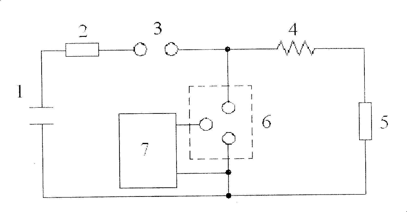
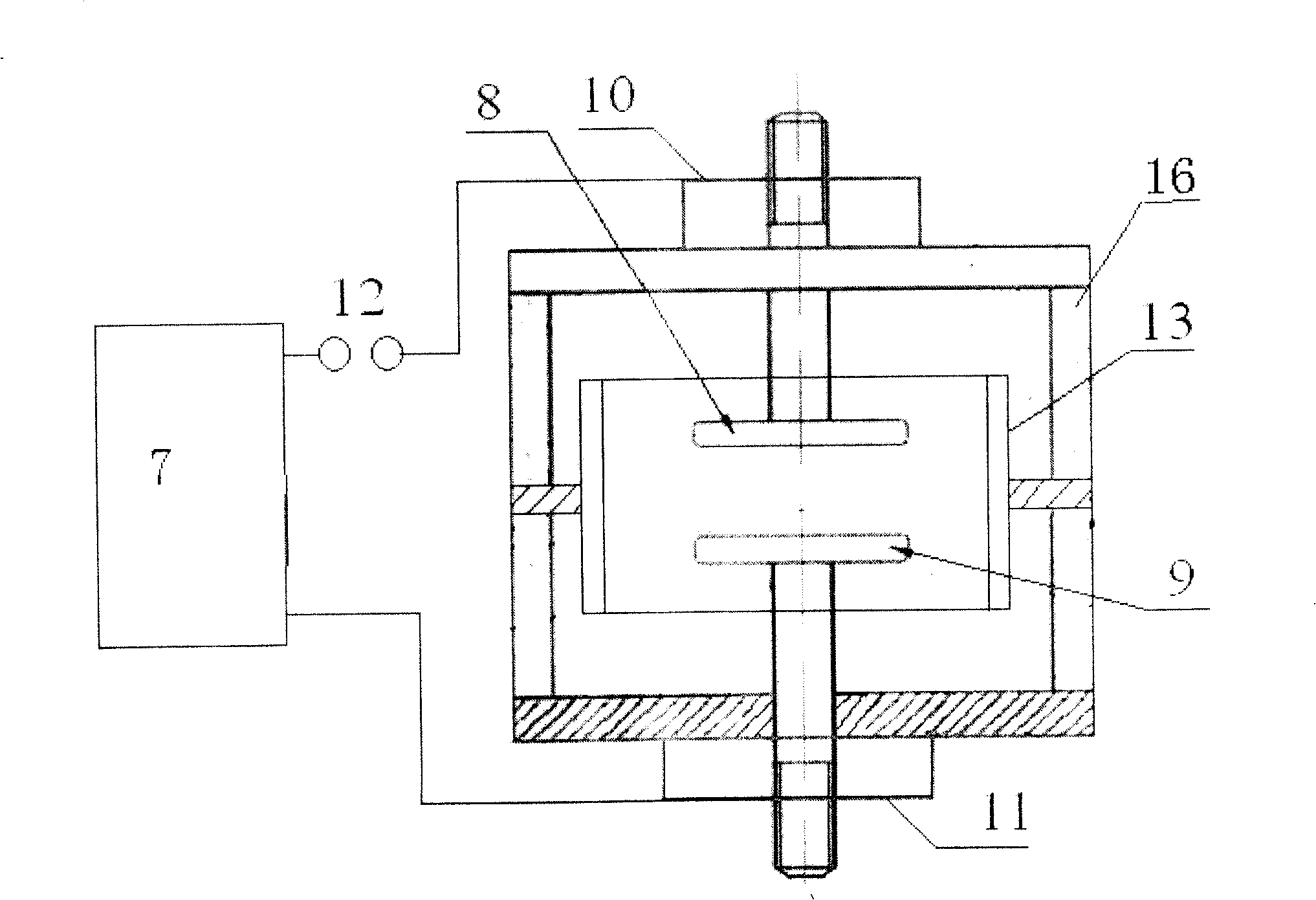
[0019] Embodiment 1: see figure 2 The short-circuit CROWBAR switch 6 includes a movable electrode 8 and a fixed electrode 9 arranged in an insulating casing 16, wherein one movable electrode 8 can be adjusted according to the discharge voltage, and the working environment of the electrodes 8 and 9 can be air or 10 -5 a~10 -2 In the vacuum environment of Pa, if it works in an air environment and short-circuits, the CROWBAR switch 6 is made of sound-absorbing materials; if it works in a vacuum environment, the CROWBAR switch 6 is made of airtight insulating materials; There are bellows which both keep the electrodes of the switch inside the insulating housing 16 and enable the electrodes to move. The connection relationship between the CROWBAR switch 6 and the trigger system is: one end of the trigger system 7 is connected to the connection terminal 10 of the movable electrode 8 of the CROWBAR switch 6 , and the other end is connected to the connection terminal 11 of the fixed...

Embodiment 2

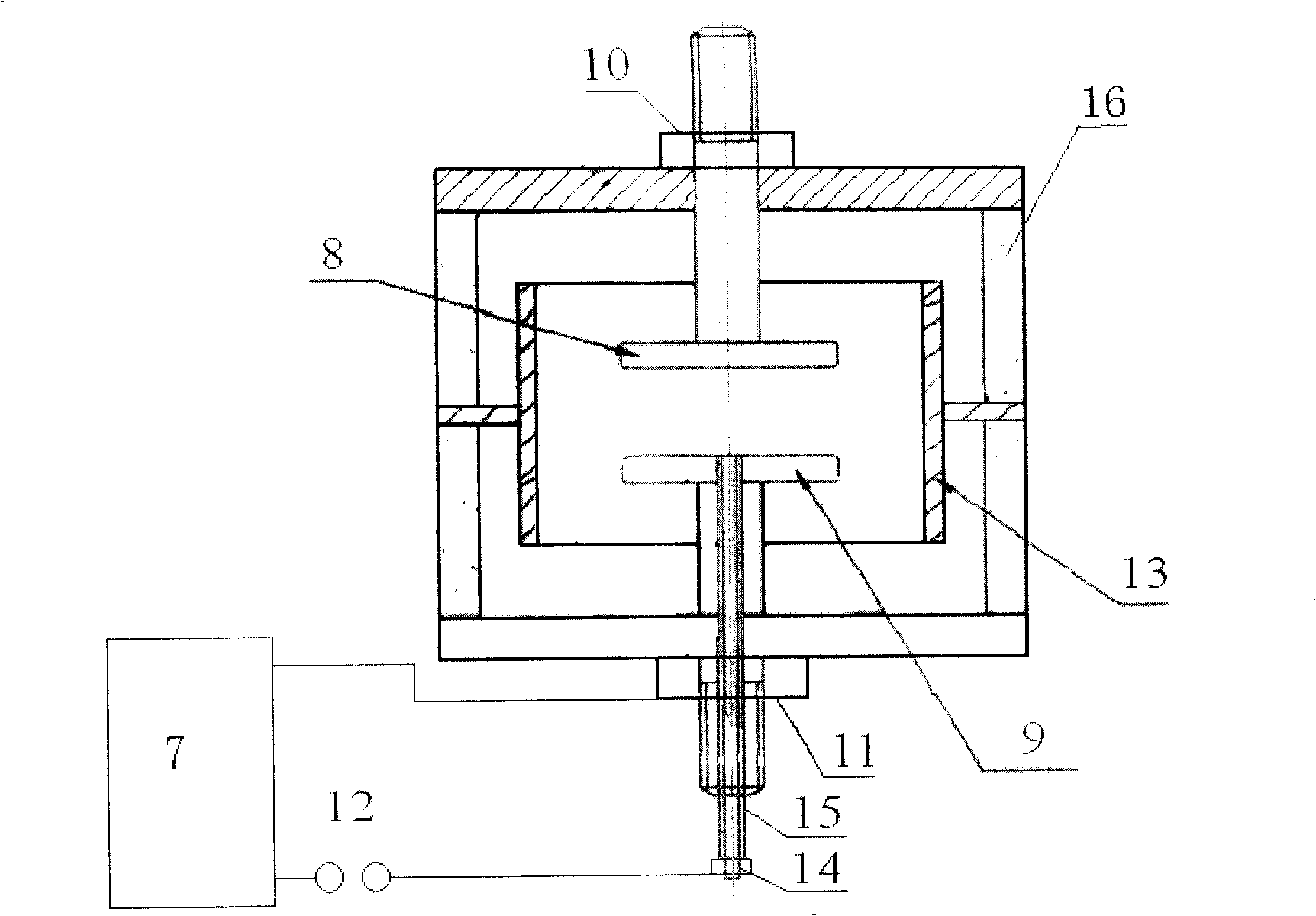
[0021] Example 2: see image 3 , the main discharge electrode and the trigger electrode of the short-circuit CROWBAR switch 6 are an integral three-electrode structure, wherein the trigger electrode 14 is embedded in the center of the fixed electrode 9, and is isolated from the fixed electrode 9 by an insulating porcelain tube 15, and the trigger electrode 14 can also be placed on the One side of the fixed electrode 9. The working environment can be air or 10 -5 Pa~10 -2In the vacuum environment of Pa, if it works in an air environment, the short-circuit CROWBAR switch 6 is made of sound-absorbing materials; if it works in a vacuum environment, the short-circuit CROWBAR switch 6 is made of airtight insulating materials, and the circuit connection between the short-circuit CROWBAR switch 6 and the trigger system Yes: one end of the trigger system 7 is connected to the trigger electrode 14 of the short-circuit CROWBAR switch 6 , and the other end is connected to the connection...

Embodiment 3

[0022] Embodiment 3: see Figure 4 , the main discharge electrode and the trigger electrode of the short-circuit CROWBAR switch 6 are an integral three-electrode structure, but the trigger electrode 14 is placed between the movable electrode 8 and the fixed electrode 9, and the trigger electrode 14 can be ring-shaped, disc-shaped or column-shaped , the line connection relation and trigger working process of the short-circuit CROWBAR switch 6 are the same as those in Embodiment 2.

[0023] The present invention is different from the most notable feature of the existing 10 / 350 impulse current test system in that it only needs to adjust the gap distance between the fixed electrode 8 and the movable electrode 9 of the short-circuit CROWBAR switch 6 (the gap distance can be changed between 0-120mm ( Air environment) or 0-20mm (vacuum environment)), the maximum withstand voltage of the CROWBAR switch can be as high as 200kV, and it can ensure that the voltage between the movable ele...


PUM


Abstract

The invention relates to a 10 / 350 impact current system of an air or vacuum CROWBAR switch, which comprises a capacity resistance connected with the power, a main discharging gap, an inductance and a resistance, wherein it coupled with a CROWBAR switch between the main discharging electrode and the capacity discharging circuit of the inductance; the CROWBAR switch comprises an active electrode and a fixed electrode or it fixes fabrics a trigger electrode in the fixed electrode or the discharging gap between the active electrode and the fixed electrode; it electric connects a trigger system between the active electrode and the fixed electrode or between the fixed electrode and the trigger electrode.

Description

technical field [0001] The invention relates to an overvoltage protector impact system, in particular to an air or vacuum short-circuit CROWBAR switch direct lightning 10 / 350μs impact current system. Background technique [0002] In recent years, with the rapid development of the information industry, people have paid great attention to the hazards caused by atmospheric overvoltage and operating overvoltage in the system. There have been a large number of reports on various electrode shapes of the I(B) level gap type spark switch as a first-level I(B) level overvoltage protection element and device. The representative ones are German PHOENIX, German OBO and French CITEL gap overvoltage protectors. [0003] I(B) gap type overvoltage protector (gap type SPD) is mainly used to withstand I(B) level direct lightning strike, and its waveform is 10 / 350μs impulse current wave. [0004] The impulse current test of I(B) gap type SPD is different from zinc oxide resistors used in pow...

Claims


Application Information

Patent Timeline
Patent Type & Authority Patents(China)
IPC IPC(8): H02M3/06G01R31/327
Inventor 陈景亮姚学玲孙伟
Owner XI AN JIAOTONG UNIV
Learn More