
Alignment mark and its producing method

A technology for alignment marks and manufacturing methods, which is applied in semiconductor/solid-state device manufacturing, photo-plate-making process of patterned surface, photo-plate-making process exposure device, etc., can solve the problem of energy not being effectively utilized, and achieve compact structure, The effect of reducing marker deformation and capturing a large range

Active Publication Date: 2009-01-28
SHANGHAI MICRO ELECTRONICS EQUIP (GRP) CO LTD
View PDF2 Cites 0 Cited by
  • Summary
  • Abstract
  • Description
  • Claims
  • Application Information

AI Technical Summary

Problems solved by technology

However, the diffraction of the periodic enhanced subdivision grating still has zero-order diffracted light, and in the grating diffraction alignment system, the zero-order diffracted light is usually blocked by the diaphragm as background light, and its energy cannot be obtained effectively. Utilization; and, the periodically subdivided enhanced alignment mark can only realize the enhancement of a high-order diffraction order light intensity at the same time

Method used


Image

  • Alignment mark and its producing method
  • Alignment mark and its producing method
  • Alignment mark and its producing method

Examples


Embodiment Construction

[0037] The present invention will be further described below in conjunction with specific embodiments and accompanying drawings, but the protection scope of the present invention should not be limited thereby.

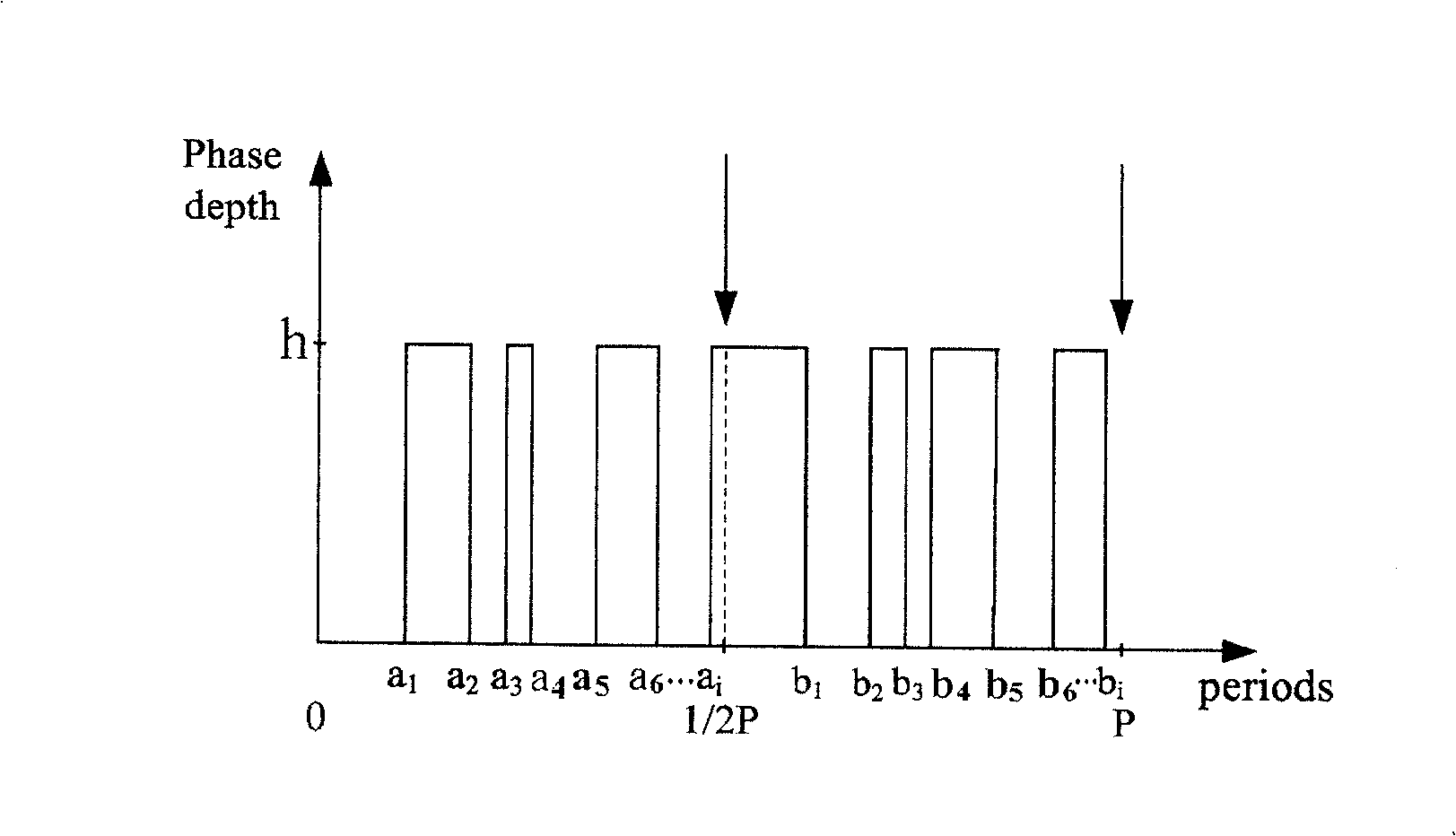
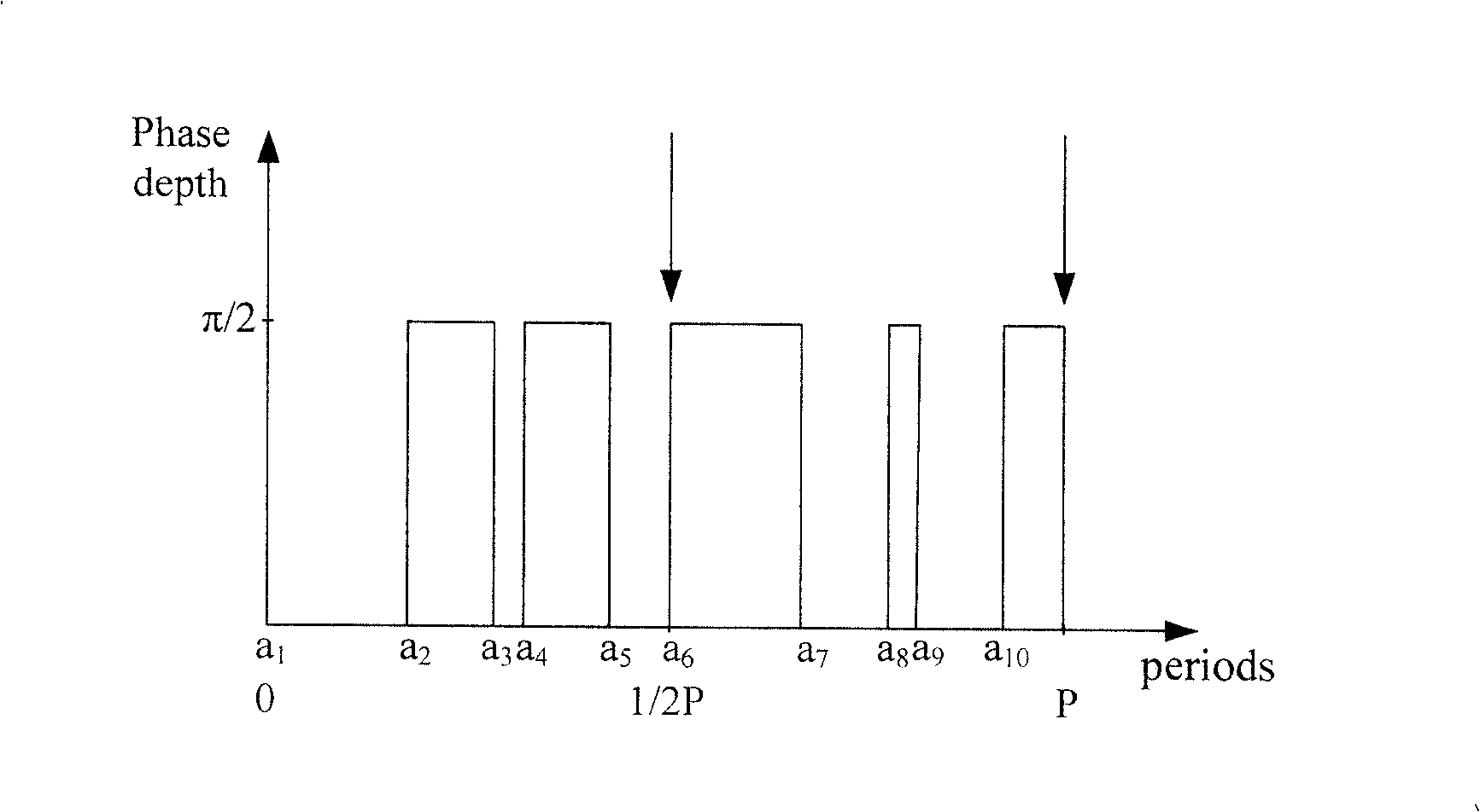
[0038] figure 1 It is a high-order diffracted light-enhanced subdivision structure of the alignment mark of the present invention. The basic principle of the high-order diffractive light-enhanced subdivision structure is based on the reflection-type Dammann grating principle of an even-numbered array.

[0039] The Damman grating is a phase grating with a special aperture function, and the Fraunhofer diffraction pattern (Fourier spectrum) produced by it on the incident light wave is a certain number of equal-intensity spots. The Damman grating can transfer the energy of the zero-order diffraction spot to the positive and negative orders of the edge. It is a Fourier transform beam splitter with high diffraction efficiency, and the light intensity uniformity of the spot...


PUM


Abstract

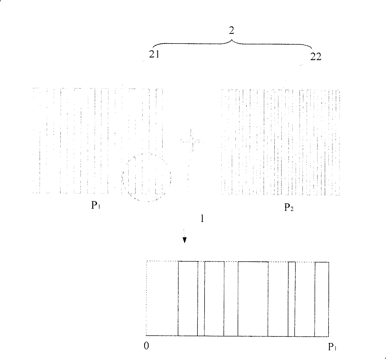
This invention provides an alignment mark and its manufacturing method, mainly uses in mask and aligent crystal plate of photoetching installing, this alignment mark includes part one and part two structure, and part two includes number one and number two grating. The periodic time of the NO.1 grating is different from NO.2 and on the each side of part one structure. The NO.1 grating is high-order diffraction light amplifier style grating, and its basic period also has some sifting structure, it can transfer zero level and even number level diffraction to the other odd number level, and at the same time it can enhance number of odd number light intensity of diffraction. Comparing to the existing technology, the alignment mark of this invention is more compaction, and it can increase alignment precision and adaptability.

Description

technical field [0001] The invention relates to a photolithographic alignment technology, in particular to an alignment mark and a manufacturing method thereof. Background technique [0002] Lithography equipment is mainly used in the manufacture of integrated circuits IC or other micro-devices. Through a photolithographic apparatus, multilayer masks with different mask patterns are sequentially imaged on a photoresist-coated wafer under precise alignment. There are currently two types of photolithography devices, one is a stepper photolithography device, the mask pattern is exposed and imaged on one exposure area of ​​the wafer, and then the wafer moves relative to the reticle to move the next exposure area to the mask pattern and projection Below the objective lens, the mask pattern is again exposed on another exposed area of ​​the wafer, and the process is repeated until all exposed areas on the wafer have an image of the mask pattern. The other type is a step-and-scan ...

Claims


Application Information

Patent Timeline
Patent Type & Authority Patents(China)
IPC IPC(8): G03F9/00G03F7/20H01L21/027
Inventor 徐荣伟李铁军
Owner SHANGHAI MICRO ELECTRONICS EQUIP (GRP) CO LTD
Learn More