Dynamic channel power equalizing control device and method in optical terminal of optical network

A technology of dynamic equalization and control devices, applied in electromagnetic wave transmission systems, electrical components, transmission systems, etc., can solve problems such as output light wavelength changes, unfavorable system automatic maintenance, and excessive number of optical channels, so as to ensure network transmission performance. Effect

Inactive Publication Date: 2009-03-25
王阳
View PDF2 Cites 2 Cited by
  • Summary
  • Abstract
  • Description
  • Claims
  • Application Information

AI Technical Summary

Problems solved by technology

[0005] Generally, the output power of the laser can be changed by adjusting the driving current of the laser in the optical transponder unit of each transmitting end in the transmitting end device, so that the pre-equalization of each optical channel can be realized. The disadvantages of this method are: (1) the output optical power of the laser Adjustment will change the wavelength of the output light, and the dynamic effect of power adjustment is also a disadvantage
Tuning while the system is running increases equipment operating risk
(2) Due to the discrete performance of lasers and electronic circuits, the detection power of each optical transponder unit is different, and the relationship between the laser drive current and output power is also different, which is not conducive to the automatic maintenance of the system
[0007] In ultra-high-density, large-capacity WDM optical transceiver equipment (such as 160-wavelength equipment), due to the large number of optical channels, the manual operation of the equipment management system for equipment performance testing and maintenance workload is huge

Method used


Image

  • Dynamic channel power equalizing control device and method in optical terminal of optical network
  • Dynamic channel power equalizing control device and method in optical terminal of optical network
  • Dynamic channel power equalizing control device and method in optical terminal of optical network

Examples


Embodiment Construction

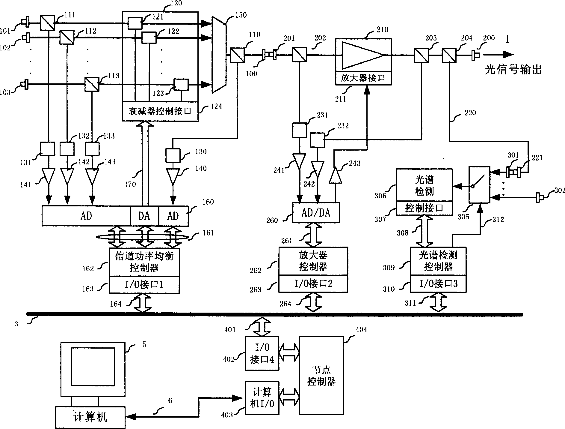
[0055] 1. Hardware device

[0056] figure 1 The structure diagram of the transmitting end of the optical transceiver with the function of dynamic channel power equalization. The optical transceiver has the function of channel power equalization, which can monitor the emission spectrum performance locally, and edit and control the transmission spectrum at the local node. figure 1 Shown in is the hardware component of unidirectional optical transmission in the end machine. If there are wavelength division multiplexed optical signals transmitted in other directions in the optical transceiver, the channel power equalization devices in other transmission directions are the same as those described in the figure.

[0057] In the optical transceiver, there are multiple optical signals from the optical forwarding unit, and these optical signals need to be combined and amplified to a suitable power for transmission. The hardware device in the optical transceiver includes the following...


PUM


Abstract

The present invention relates to densified wavelength division multiplexing optical terminal equipment in optical communication network. The present invention has integrated attenuator array set in the emitting end and the receiving end for regulation, and is suitable for both wavelength division multiplexing optical terminal with opened light interface and optical terminal with integrated light interface. By means of the power value of optical terminal as a static work point performance and the similarity between the practical light channel power spectrum and the target power spectrum, automatically regulating optical system is constituted through iterative control, detection, analysis and control. Regulating network spectrum in real time and dynamically can ensure the stable network transmission performance.

Description

technical field [0001] The invention relates to a device and method for realizing channel power dynamic balance control of an optical network optical transceiver. Specifically, it is a device and method for realizing dynamic balance adjustment and control of optical channel power of different central wavelengths in a wavelength division multiplexing optical network optical terminal, especially related to dense wavelength division multiplexing optical network optical terminal equipment in the field of communication. The present invention can be used The channel power distribution of the optical transceiver in the optical network is dynamically adjusted. Background technique [0002] Dense Wavelength Division Multiplexing (DWDM) optical fiber communication technology is developing towards ultra-long, ultra-high-speed, large-capacity, and dynamically configurable networking, which puts forward higher and higher requirements for optical channel power control technology. In a DW...

Claims


Application Information

Patent Timeline
Patent Type & Authority Patents(China)
IPC IPC(8): H04J14/02H04B10/18H04B10/08H04B10/07H04B10/294
Inventor 王加莹
Owner 王阳
Why Eureka
Try Eureka