Dc-dc converter

A technology of power converters and generators, which is applied in the direction of output power conversion devices, DC power input conversion to DC power output, instruments, etc., and can solve problems such as irregular current interference

Active Publication Date: 2009-04-08
III HLDG 6
View PDF3 Cites 3 Cited by
  • Summary
  • Abstract
  • Description
  • Claims
  • Application Information

AI Technical Summary

Problems solved by technology

[0005] A disadvantage of prior art buck converters is that, for small duty cycle values, the control of the switch-off instant is disturbed by irregularities in the measured current

Method used


Image

  • Dc-dc converter
  • Dc-dc converter
  • Dc-dc converter

Examples


Embodiment Construction

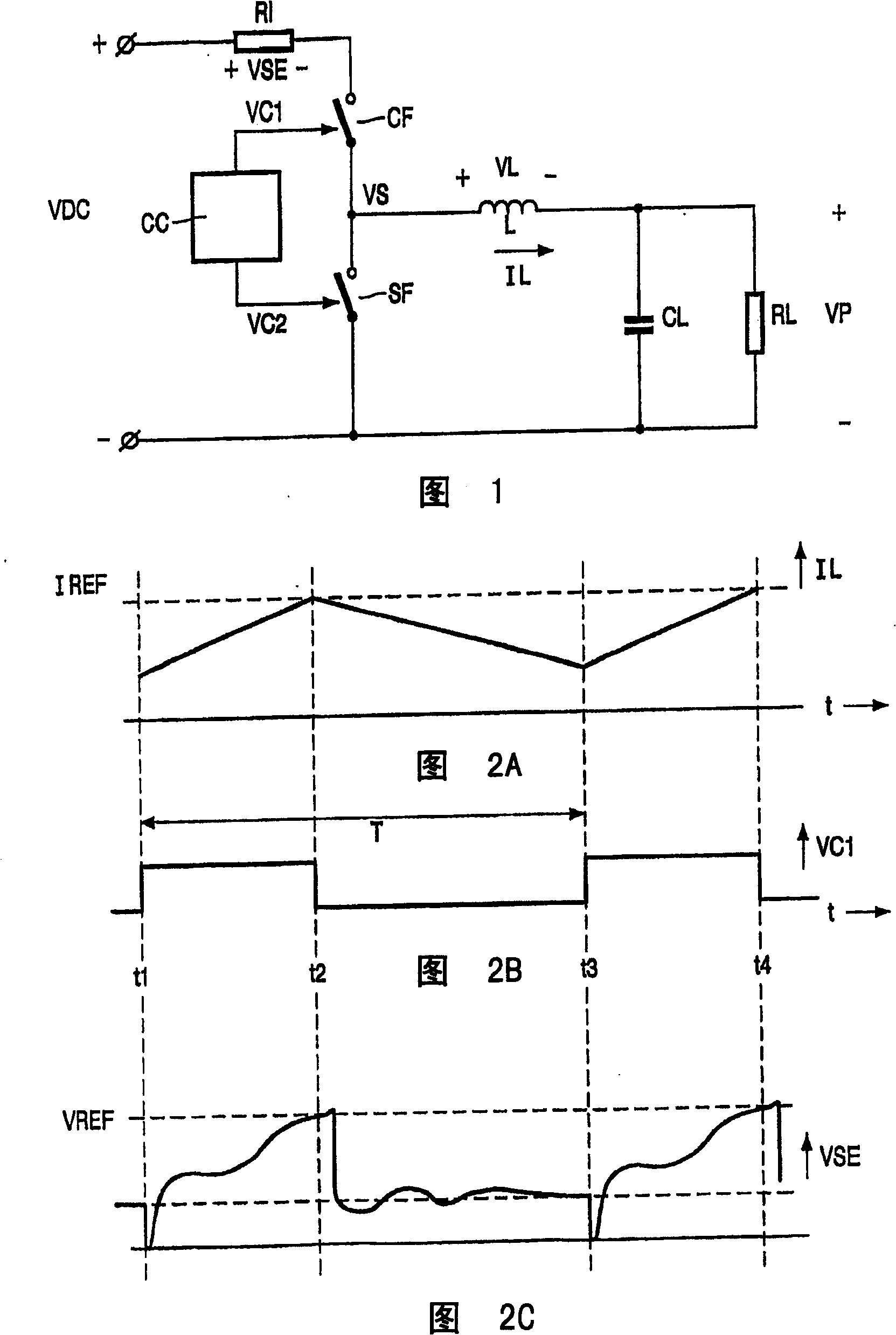
[0035] Figure 1 shows a prior art buck converter. A series arrangement of resistor R1 and controllable switches CF and SF is used to receive a DC input voltage VDC. The connection point of the switches CF and SF is connected to the load RL through the inductance L. Smoothing capacitor CL is connected in parallel with load RL. The control circuit CC controls the switches CF and SF with switching signals VC1 and VC2, respectively. The voltage across the inductor L is denoted by VL, and the current through the inductor L is denoted by IL. The voltage at the junction of the switches CF and SF is VS, and the voltage across the load RL is VP. The operation of a step-down converter is explained based on the waveforms shown in Figure 2.

[0036] 2A-2C show waveforms used to illustrate a prior art buck converter operating in continuous mode. FIG. 2A shows the current IL through the inductor L, FIG. 2B shows the control voltage VC1 controlling the switch CF, and FIG. 2C shows the v...


PUM


Abstract

A power converter comprises an inductor (LP) and a controllable switch (CF) coupled to the inductor. A switch controller (1) supplies a periodic switching signal (VC1) which has a repetition time and a duty cycle to the controllable switch (CF) to generate a periodical inductor current (IL) through the inductor. A generator (2) generates an emulated signal (IE) based on timing information (TI) which represents the repetition time and the duty cycle to emulate a current signal being representative of the inductor current. A comparator (3) compares the emulated signal (IE) with the current signal (CS) to obtain an error signal (E). A generator controller (4) receives the error signal (E) to supply a control signal (VD) to the generator (2) to adapt a property of the emulated signal (IE) to become substantially equal to a property of the current signal (CS).

Description

technical field [0001] The present invention relates to a power converter, and to a multi-phase step-down converter. Background technique [0002] A step-down converter in the prior art includes a series arrangement of a resistor and a plurality of controllable switches. The series arrangement is for receiving a DC input voltage. The connection point of the switch is connected to a load through an inductor, and a smoothing capacitor is connected in parallel with the load. A control circuit controls the closing and opening cycles of the switch. The control circuit controls the switches in such a way that only one switch is always conducting. [0003] When a first of the switches is closed to connect the inductor to the positive pole of the DC input voltage, the current through the inductor increases linearly. When the current passing through the inductor exceeds the reference level, the controller turns off the first switch and closes other switches, so that the current p...

Claims


Application Information

Patent Timeline
IPC IPC(8): H02M3/335H02M3/158H02M1/00H02M3/155H02M3/156
CPCH02M3/156
Inventor J·C·哈伯斯塔德特G·范德霍尔恩
Owner III HLDG 6
Why Eureka
Try Eureka