Design of cross coupling in filter and its preparation method
A cross-coupling and filter technology, applied in impedance networks, electrical components, multi-terminal-pair networks, etc., can solve problems such as simplicity, limited ability to carry power, and no analysis, design, and debugging methods.
- Summary
- Abstract
- Description
- Claims
- Application Information
AI Technical Summary
Problems solved by technology
Method used
Image
Examples
Embodiment 1
[0137] Eight-pole resonant cavity filter, its structure diagram is shown in Figure 18 , which is the combined structure of Figure 5(e) and Figure 5(f). It is known from the previous analysis that Fig. 5(e) shows a four-resonator unit filter with inductive double-cross coupling. There are two transmission zeros at the high-end band of the transmission passband, and there is no transmission zero at the low-end. Figure 9 The solid line; Figure 5(f) shows a four-resonator unit filter with inductive and capacitive double-cross coupling, which contains two transmission zeros at the low end of the transmission passband, and no transmission zero at the high end, and its transmission characteristics are shown in Figure 10 The solid line of , therefore, Figure 18 The filter transmission characteristic of the structural form contains four transmission zeros, among which the two transmission zeros generated by resonators 1~4 are located at the low end band edge of the passband, and t...
Embodiment 2
[0139] Ten-pole resonator filter, its structure diagram is shown in Figure 20 , the resonators 1 and 10 are connected to the input and output ports, and the main coupling between the resonators is capacitive coupling. Using the cross-coupling phase analysis model provided by the present invention to analyze its transmission zero characteristics is as follows.
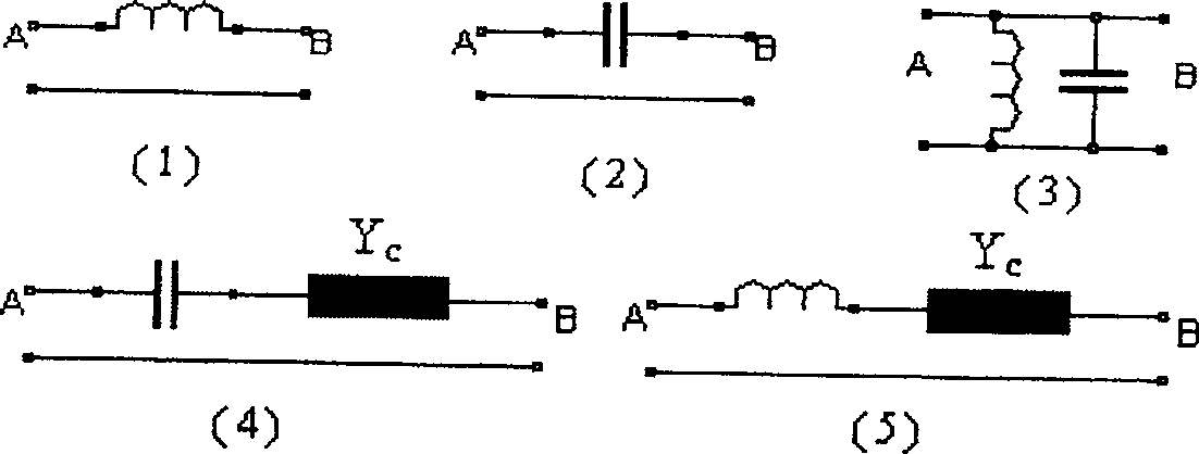
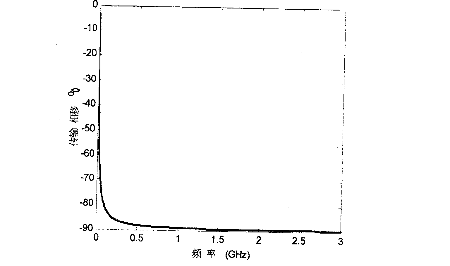
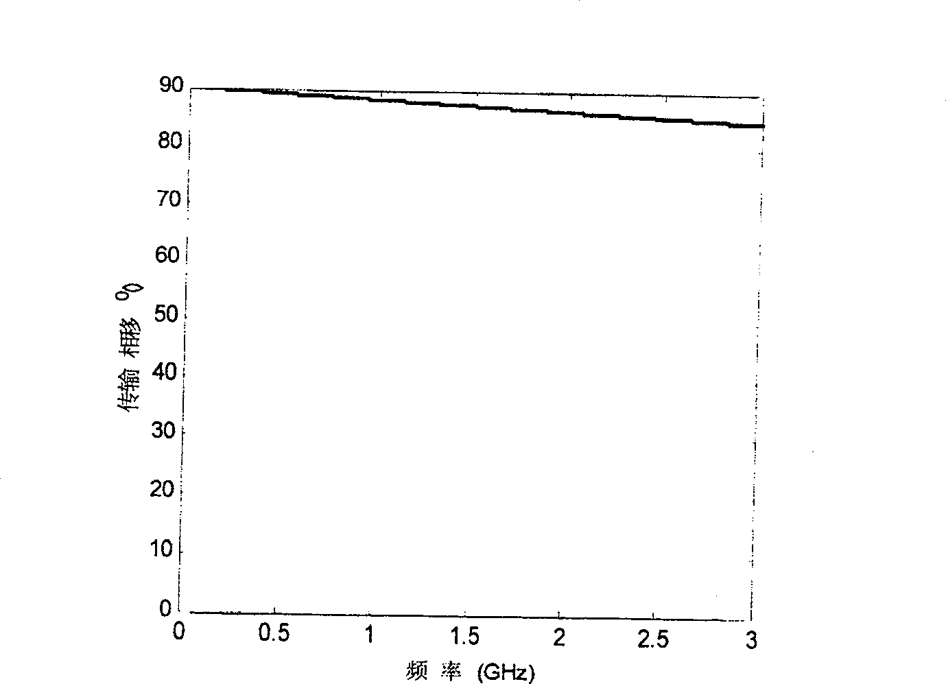
[0140] At the low end of the resonant frequency of the resonator unit 3, the transmission channel (2→3→4 phase shift: +90 0 +90 0 +90 0 =+270 0 ) with cross-coupled channels (2→4 phase shift: -90 0 ) have the same phase shift, so there is no transmission zero at the low end of the transmission passband; at the high end of the resonant frequency of the resonator unit 3, the transmission channel (2 → 3 → 4 phase shift: +90 0 -90 0 +90 0 =+90 0 ) with cross-coupled channels (2→4 phase shift: -90 0 ) The phase shift between ) is opposite, so a transmission zero point is generated at the high-end band edge of the t...
Embodiment 3
[0146] A coaxial resonant cavity filter made of aluminum alloy is designed, the physical model is shown in Figure 22 . Four coaxial resonant cavities are opened in the aluminum alloy box, and the input / output devices (I / O and O / I) connected to the coaxial resonant cavities are coaxial probes. The tuning screw, in addition to the main signal channel between the coaxial resonators, a rectangular auxiliary signal channel is opened between the head and tail coaxial resonators, and a quarter-wavelength rectangular strip line is laid in the rectangular slot as a crossover Coupling control unit (1).
[0147] The coupled phase relationship model of the filter is shown in Figure 5(c), which is a four-resonator unit filter with capacitive cross-coupling. Application of the cross-coupling phase analysis model provided by the present invention to analyze the coupling of the filter of this structure and the relative phase relationship of cross-coupling shows that at the low end of the r...
PUM
 Abstract
Description
Claims
Application Information
 - R&D
- Intellectual Property
- Life Sciences
- Materials
- Tech Scout
- Unparalleled Data Quality
- Higher Quality Content
- 60% Fewer Hallucinations
Browse by: Latest US Patents, China's latest patents, Technical Efficacy Thesaurus, Application Domain, Technology Topic, Popular Technical Reports.
© 2025 PatSnap. All rights reserved.Legal|Privacy policy|Modern Slavery Act Transparency Statement|Sitemap|About US| Contact US: help@patsnap.com


