Design of cross coupling in filter and its preparation method

A cross-coupling and filter technology, applied in the direction of impedance network, electrical components, multi-terminal pair network, etc., can solve the problem of not being able to meet the requirements of low insertion loss of communication equipment, increasing the cost of equipment, and not giving analysis, design and debugging methods And other issues

Inactive Publication Date: 2005-05-25
UNIV OF ELECTRONIC SCI & TECH OF CHINA
View PDF3 Cites 29 Cited by
  • Summary
  • Abstract
  • Description
  • Claims
  • Application Information

AI Technical Summary

Problems solved by technology

However, such efforts are generally purely as uncontrolled parasitic effects, as described in U.S. Patent No. 5,616,539 to Hey-Shipton et al., but these efforts are limited to the design of some specific filter devices, and no simple and low-cost solutions are given. Generic Design and Implementation Methodology
[0008] The Chinese patent application with application number 00806534.9 and publication number CN 1352814A discloses a method for microstrip cross-coupling control equipment, which is suitable for transmission band filters, but does not provide a simple and general analysis, design and debugging method, and There are also the following disadvantages: (1), its ability to carry power is very limited, and cannot meet the requirements of high power carrying capacity in specific occa

Method used


Image

  • Design of cross coupling in filter and its preparation method
  • Design of cross coupling in filter and its preparation method
  • Design of cross coupling in filter and its preparation method

Examples


Embodiment 1

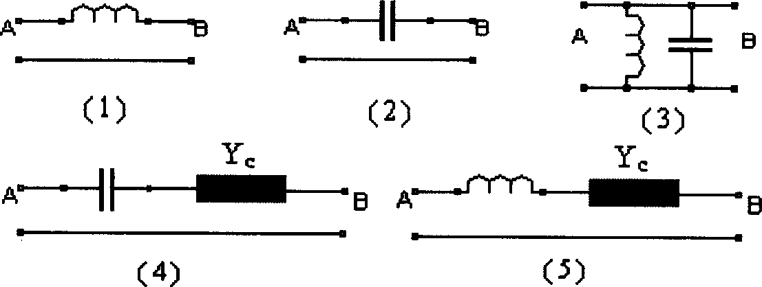
[0137] Eight-pole resonant cavity filter, its structure diagram is shown in Figure 18 , which is the combined structure of Figure 5(e) and Figure 5(f). It is known from the previous analysis that Fig. 5(e) shows a four-resonator unit filter with inductive double-cross coupling. There are two transmission zeros at the high-end band of the transmission passband, and there is no transmission zero at the low-end. Figure 9 The solid line; Figure 5(f) shows a four-resonator unit filter with inductive and capacitive double-cross coupling, which contains two transmission zeros at the low end of the transmission passband, and no transmission zero at the high end, and its transmission characteristics are shown in Figure 10 The solid line of , therefore, Figure 18 The filter transmission characteristic of the structural form contains four transmission zeros, among which the two transmission zeros generated by resonators 1~4 are located at the low end band edge of the passband, and t...

Embodiment 2

[0139] Ten-pole resonator filter, its structure diagram is shown in Figure 20 , the resonators 1 and 10 are connected to the input and output ports, and the main coupling between the resonators is capacitive coupling. Using the cross-coupling phase analysis model provided by the present invention to analyze its transmission zero characteristics is as follows.

[0140] At the low end of the resonant frequency of the resonator unit 3, the transmission channel (2→3→4 phase shift: +90°+90°+90°=+270°) and the cross-coupling channel (2→4 phase shift: -90° ) have the same phase shift, so there is no transmission zero at the low end of the transmission passband; at the high end of the resonant frequency of the resonator unit 3, the phase shift of the transmission channel (2→3→4: +90°-90°+90° =+90°) is opposite to the phase shift between cross-coupling channels (2→4 phase shift: -90°), so a transmission zero point is generated at the high-end band edge of the transmission passband. ...

Embodiment 3

[0146] A coaxial resonant cavity filter made of aluminum alloy is designed, the physical model is shown in Figure 22 . Four coaxial resonant cavities are opened in the aluminum alloy box, and the input / output devices (I / O and O / I) connected to the coaxial resonant cavities are coaxial probes. The tuning screw, in addition to the main signal channel between the coaxial resonators, a rectangular auxiliary signal channel is opened between the head and tail coaxial resonators, and a quarter-wavelength rectangular strip line is laid in the rectangular slot as a crossover Coupling control unit (1).

[0147] The coupled phase relationship model of the filter is shown in Figure 5(c), which is a four-resonator unit filter with capacitive cross-coupling. Application of the cross-coupling phase analysis model provided by the present invention to analyze the coupling of the filter of this structure and the relative phase relationship of cross-coupling shows that at the low end of the r...


PUM


Abstract

This invention provides the design of cross coupling in filter and method for preparing the same. Which is based on coupling relation mode and determining transmission zero number and relative position by analyzing relative phase shifting relation, according to cross coupling realizing method selecting and optimizing cross coupling parts, based on filter adjusting method determining resonance frequency distribution property, coupling parts parameter, so quick and accurate debugging resonator unit and coupling part parameters.

Description

technical field [0001] This invention relates to filters for electrical signals, and more particularly to the design and preparation of cross-coupling in narrowband filters. Background technique [0002] Narrowband filters are especially useful in modern communications, especially wireless communications. With the rapid development of communications, spectrum resources are increasingly scarce and market competition is increasingly intensified, how to simultaneously accommodate multiple communication signals in a limited frequency band and reduce interference to other devices, in order to effectively use limited frequency resources, is Important issues faced in communication system design and equipment development. Therefore, communication systems urgently need a large number of low-cost, small-volume, low-insertion-loss high-performance narrow-band filter devices. [0003] In particular, some high-power and high-performance filter devices are widely used in base stations o...

Claims


Application Information

Patent Timeline
IPC IPC(8): H03H7/00H03H7/01
Inventor 李忻聂在平
Owner UNIV OF ELECTRONIC SCI & TECH OF CHINA
Why Eureka
Try Eureka