Liquid-collecting energy absorption device

A technology of energy absorber and energy absorbing plate, which is applied in the field of liquid catcher energy absorber, can solve problems such as unfavorable liquid, violent fluctuation of liquid level at the bottom of the tower, and increase of light component content at the bottom of the tower, so as to reduce the flow velocity, The effect of eliminating liquid phase back-mixing and improving operating efficiency

Inactive Publication Date: 2009-05-20
TIANJIN UNIV
View PDF4 Cites 1 Cited by
  • Summary
  • Abstract
  • Description
  • Claims
  • Application Information

AI Technical Summary

Problems solved by technology

[0004] However, after being applied in various large-scale towers in recent years, it is found that although the double tangential circulation gas distributor can obviously improve the initial distribution of the gas entering the tower, the high-speed gas entering the tower in the horizontal direction passes through the double tangential circulation. The gas distributor then turns downward, causing the liquid level at the bottom of the tower to fluctuate violently under the impact of the high-speed gas, and even part of the liquid is entrained by the high-speed flowing gas to the mass transfer area, and the high-speed droplet group also entrains part of the light gas into the mass transfer area. At the bottom of the tower, the content of light components at the bottom of the tower increases, and it is difficult to ensure the quality of the product at the bottom of the tower, resulting in a decrease in the operating efficiency of the tower, and this structure is also not conducive to the smooth flow of the liquid entrained in the gas entering the tower into the bottom of the tower, so , the double tangential circulation gas distributor cannot reasonably solve the problem of liquid entrainment in the inlet gas at the bottom of the tower

Method used


Image

  • Liquid-collecting energy absorption device
  • Liquid-collecting energy absorption device
  • Liquid-collecting energy absorption device

Examples


Embodiment 1

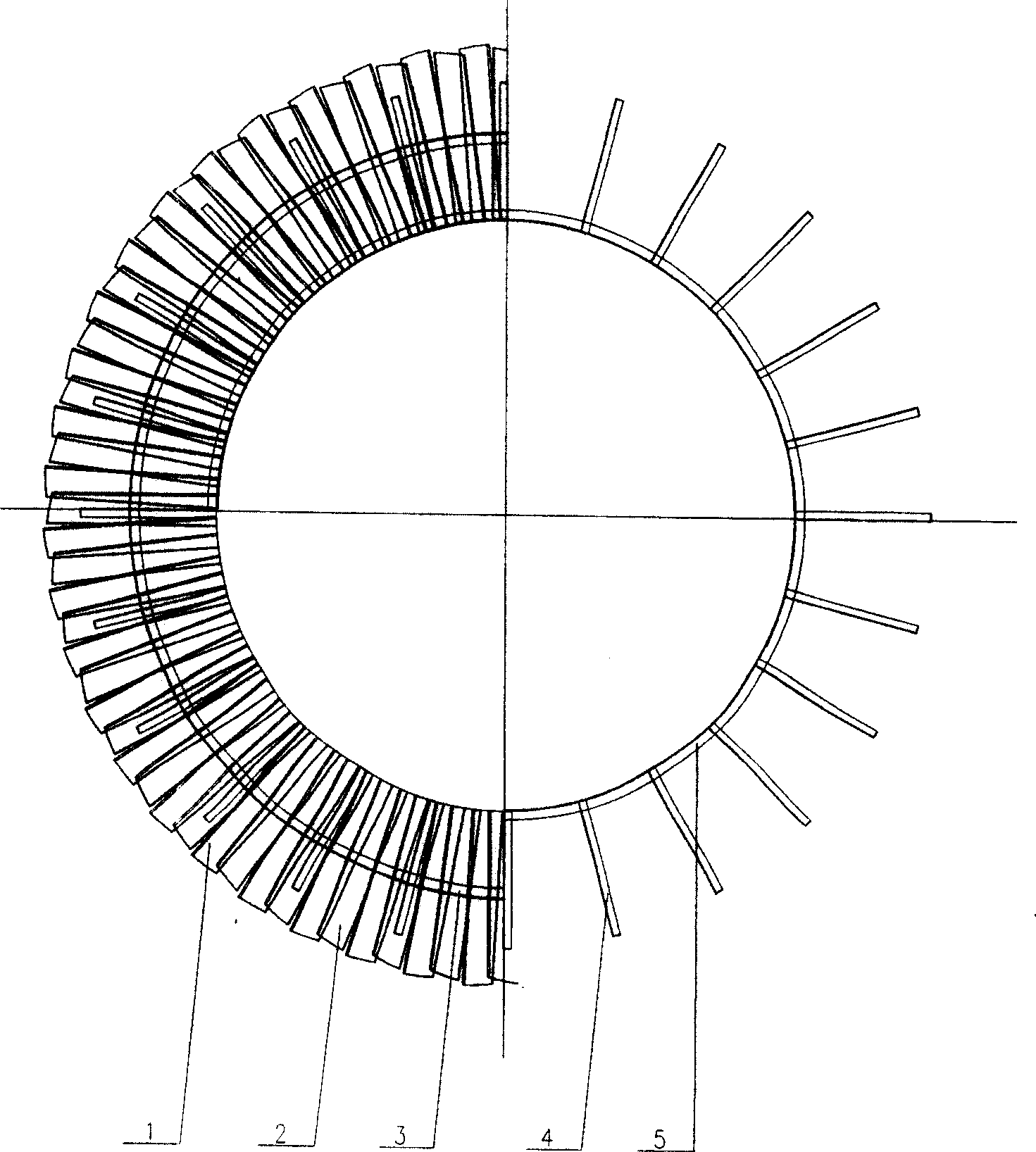
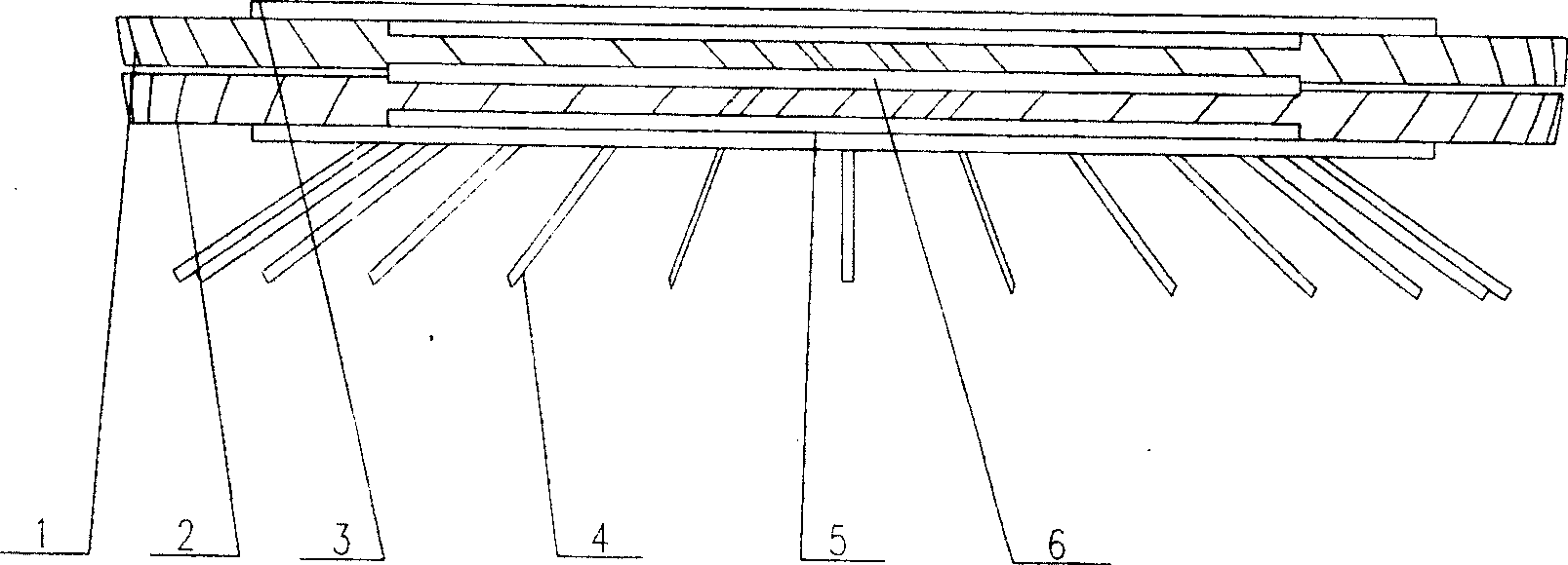
[0023] Such as figure 1 , 2 As shown, the new liquid trapping energy absorber is ring-shaped as a whole, and the upper liquid trapping energy absorbing plate 1 and the lower liquid trapping energy absorbing plate 2 are connected through the upper layer annular angle steel 3, the lower layer annular angle steel 5 and the annular rib plate 6 of the annular angle steel. One end of the supporting angle steel 4 is directly welded on the lower annular angle steel 5, the other end is welded on the tower wall, and the outer edge of the liquid-catching energy-absorbing plate is directly welded on the tower wall.

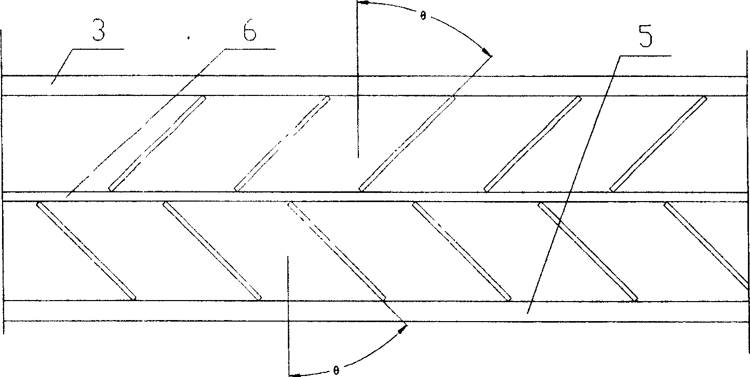
[0024] The upper liquid-catching and energy-absorbing plate 1 can be a rectangular plate or a trapezoidal plate, and is evenly distributed according to the circumference. The upper liquid-catching energy-absorbing plate 1 forms a certain angle relative to the tower body, such as image 3 As shown, the effect of capturing liquid and absorbing energy can be better achieved. ...

Embodiment 2

[0028] The difference from Example 1 is that the bottom of the lower liquid-catching energy-absorbing plate 2 can be provided with a horizontal flap when the gas flow rate is relatively high, so as to slow down the impact of the high-speed gas on the still liquid, such as Figure 4 shown.

Embodiment 3

[0030] The difference from Example 1 is that the upper liquid-catching energy-absorbing plate and the lower liquid-catching energy-absorbing plate are herringbone baffles, and the angles thereof are between 0 degrees and 180 degrees, such as Figure 5 As shown, according to the uniform distribution on the circumference, the number can be converted from the flow area according to the size of the gas flow velocity, and the positions of the upper and lower layers of herringbone baffles are staggered.

[0031] The novel liquid trapping energy absorber described in the present invention is applied to the bottom of a large tower in conjunction with a double tangential circulation gas distributor. It has been practically applied in many towers at present. The results of the application show that:

[0032] The present invention has the following characteristics:

[0033] 1. The new energy absorber for liquid capture can capture the liquid droplets mixed in the intake air at the bottom...


PUM


Abstract

The invention relates to a liquid-catching power absorber. It comprises liquid-catching power absorbing plate and annular mounting plate; said liquid-catching power absorbing plate includes upper layer liquid-catching power absorbing plate 1 and lower layer liquid-catching power absorbing plate 2, between two said plates equipped with a annular plate 6, the upper of upper layer liquid-catching power absa orbing plate is connected with upper layer annular plate 3, while the one at lowe layer iconnected with lower layer annular plate 5; supporting stand 4 is installed on lower layer annular plate 5, the other end of supporting stand is welded on tower wall. The liquid-catching power absorber greatly reduces flowing speed of gas from circulating gas distributor, eliminates impact to liquid surface in tower bottom by gas and entrainment, and the liquid in gas is catched by said two liquid-catching power absorbing plate, which avoids back-mix-flow and increases operating efficiency.

Description

technical field [0001] The invention relates to an internal part of a rectification tower, in particular to a liquid-catching energy absorber. technical background [0002] In the departments of oil refining, petrochemical, fine chemical, food, medicine and environmental protection, towers are important unit equipment with a large volume and wide range, and their investment generally accounts for about 20% of the total investment, and some even as high as 50%. Columns are widely used in unit operations such as distillation, absorption, extraction, washing, and heat transfer. Therefore, the research on towers has always been an important issue that scholars at home and abroad have generally paid attention to. [0003] With the development of tower equipment, the technology of tower internals has also been continuously developed and improved. Various new structures of tower internals emerge in an endless stream, especially the continuous improvement of gas distributors has fu...

Claims


Application Information

Patent Timeline
Patent Type & Authority Patents(China)
IPC IPC(8): B01D3/32B01D47/14B01D53/18
Inventor 姜斌张吕鸿许长春罗铭芳许力强张志恒
Owner TIANJIN UNIV
Why Eureka
Try Eureka