
Device for preventing hydraulic rock breaker against scuffing

A technology of hydraulic pistons and rock breakers, which is applied in the direction of striking tools, light impact tools, manufacturing tools, etc., can solve the problems of increased oil leakage, easy wear, and increased friction surface gaps, etc., to reduce oil leakage , prevent scratches, prevent damage

Active Publication Date: 2009-06-03
SOOSAN HEAVY IND CO LTD
View PDF8 Cites 1 Cited by
  • Summary
  • Abstract
  • Description
  • Claims
  • Application Information

AI Technical Summary

Problems solved by technology

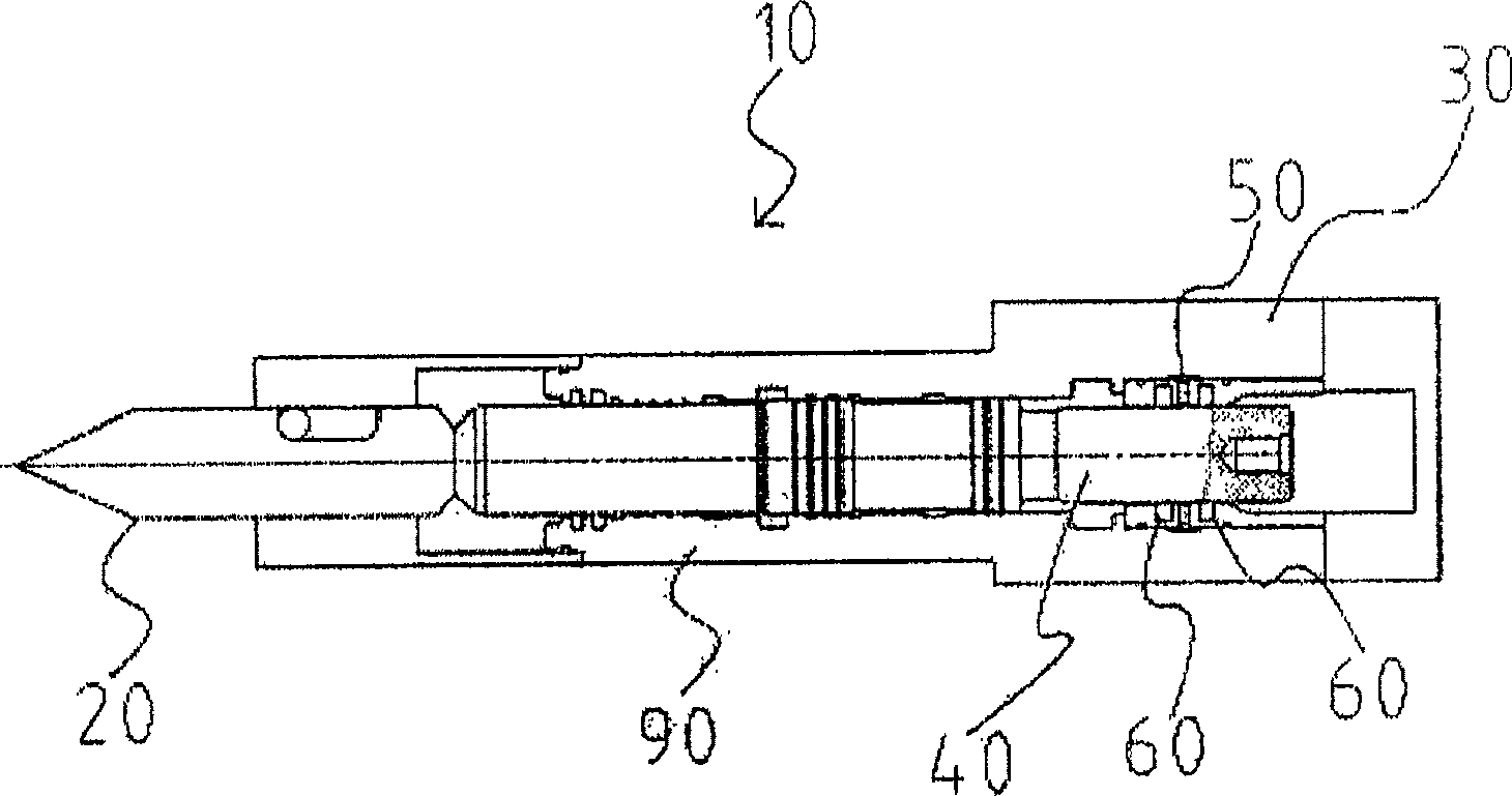
[0005] However, the above-mentioned hydraulic lithotripter 10 produces violent vibrations along with the crushing action of the chisel 20, and the outer surface of the above-mentioned retainer 30 and the hydraulic piston 40 which is arranged inside and rubs against each other is prone to wear due to the above-mentioned severe vibrations, thereby increasing Reduce the maintenance cost of the hydraulic piston, and increase the friction surface gap between the above-mentioned retainer 30 and the hydraulic piston 40, resulting in an increase in oil leakage
[0006] Especially in the gap between the above-mentioned retaining ring 30 and the friction surface of the hydraulic piston 40, impurities such as iron filings or dust caused by friction are likely to be generated, thereby causing scratches and wear on the outer surface of the above-mentioned hydraulic piston 40, which greatly shortens the life of the hydraulic piston.
The sealing member 60, which is arranged between the above-mentioned retainer 30 and the friction surface of the hydraulic piston 40 and is used for sealing, has a low-pressure pipeline 50 in the middle, and a high pressure is applied to the sealing member 60 at the chisel 20, resulting in the above-mentioned chisel part. Seal 60 is prone to breakage

Method used


Image

  • Device for preventing hydraulic rock breaker against scuffing
  • Device for preventing hydraulic rock breaker against scuffing
  • Device for preventing hydraulic rock breaker against scuffing

Examples


Embodiment Construction

[0020] Hereinafter, preferred embodiments of the present invention will be described in detail with reference to the accompanying drawings.

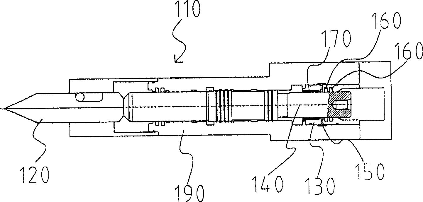
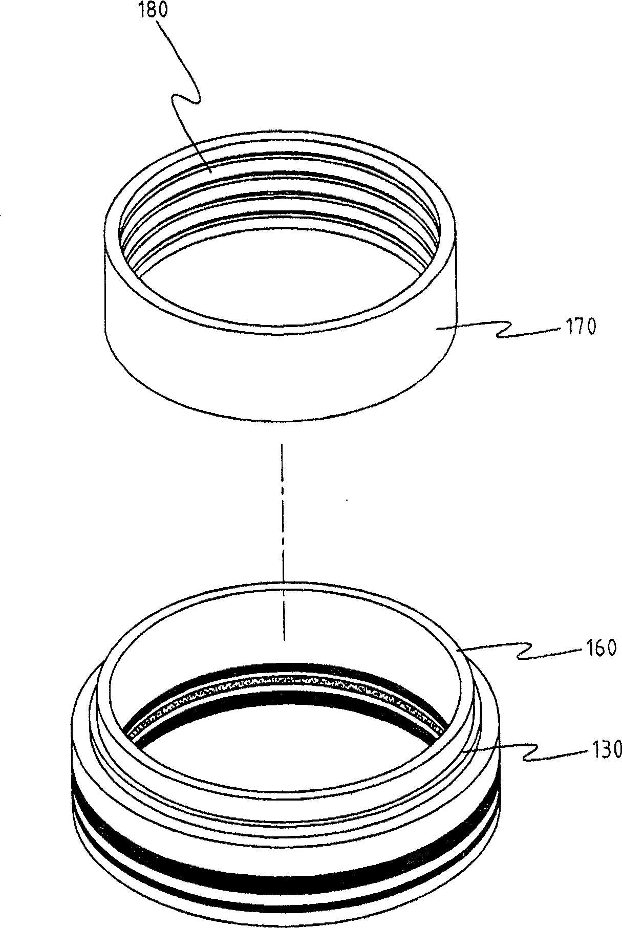
[0021] figure 2 It is a schematic front sectional view of the device for preventing the hydraulic lithotripter piston from being scratched according to the present invention, image 3 and Figure 4 It is a perspective view and a partially enlarged schematic view of the bush integrated with the retainer in the present invention. Below the cylinder 190 of the hydraulic lithotripter 110, a chisel 120 for crushing objects is arranged, and the retainer 130 is arranged inside the cylinder 190 on the upper side of the above-mentioned chisel 120, and a hydraulic piston 140 is arranged on its inner side and moves up and down to strike The chisel 120 is provided with a low-pressure pipeline 150 and a sealing member 160 between the retaining ring 130 and the friction surface of the hydraulic piston 140 .

[0022] The above-mentioned hydraulic p...


PUM


Abstract

The invention relates to a device for preventing a hydraulic pressure lithotripter piston from being scored, i.e., preventing friction between a hydraulic pressure piston and a protection ring by integrlly-forming a bush made of a non-iron metal material having a hardness lower than that of the hydraulic pressure piston on an inner side friction plane of the protection ring which moves up and down in the hydraulic pressure piston; reducing a clearance between the hydraulic pressure piston and the bush to a minimum thereby reducing oil leakage; preventing the hydraulic pressure piston from being scored by forming a labyrinth type recess in an inner face of the bush on inner side friction plane of the protection ring and capturing impurities between the bush and the hydraulic pressure piston, and prolonging a life time of the hydraulic pressure piston; arranging a sealing member behind a low-pressure pipeline to prevent damages of the sealing member.

Description

technical field [0001] The invention relates to a device for preventing the piston of a hydraulic breaker from being scratched, which can prevent the abrasion caused by the friction between the hydraulic piston and the retaining ring in the hydraulic breaker, and can prevent the hydraulic piston from being scratched. The friction part with the retainer (Retainer) is mixed with impurities to cause scratches. In particular, the bush (Bush) made of a non-ferrous metal material with a hardness lower than that of the above-mentioned hydraulic piston is integrally formed inside the hydraulic piston. The internal friction surface of the retainer for rising and falling movements; and the inner surface of the bushing arranged on the internal surface of the above-mentioned retaining ring is formed with a large number of labyrinth (Labyrinth) grooves, which are used to catch when the above-mentioned hydraulic piston rises and falls. Impurities such as iron filings or mixed dust generated...

Claims


Application Information

Patent Timeline
Patent Type & Authority Patents(China)
IPC IPC(8): B25D17/10B25D9/00
Inventor 李一材
Owner SOOSAN HEAVY IND CO LTD
Learn More