Emusified coking-slurry lean-oxygen burner

A technology of oxygen-poor combustion and coke slurry, which is applied in the direction of burners, combustion chambers, combustion methods, etc., can solve problems such as complex structures and processes, and achieve the effects of reducing the formation of nitrogen oxides, avoiding coking, and high combustion temperatures

Inactive Publication Date: 2009-06-17
GUANGZHOU DEVOTION THERMAL TECH
View PDF10 Cites 0 Cited by
  • Summary
  • Abstract
  • Description
  • Claims
  • Application Information

AI Technical Summary

Problems solved by technology

It can be seen from the above that, firstly, this kind of burner structure is only suitable for the combustion of pulverized coal and not suitable for the combustion of emulsified coke slurry; secondly, this kind of burner oxidizes nitrogen through a special oxygen-deficient pyrolysis zone The substance is reduced to molecular nitrogen, and its structure and process are complex

Method used


Image

  • Emusified coking-slurry lean-oxygen burner
  • Emusified coking-slurry lean-oxygen burner

Examples


Embodiment 1

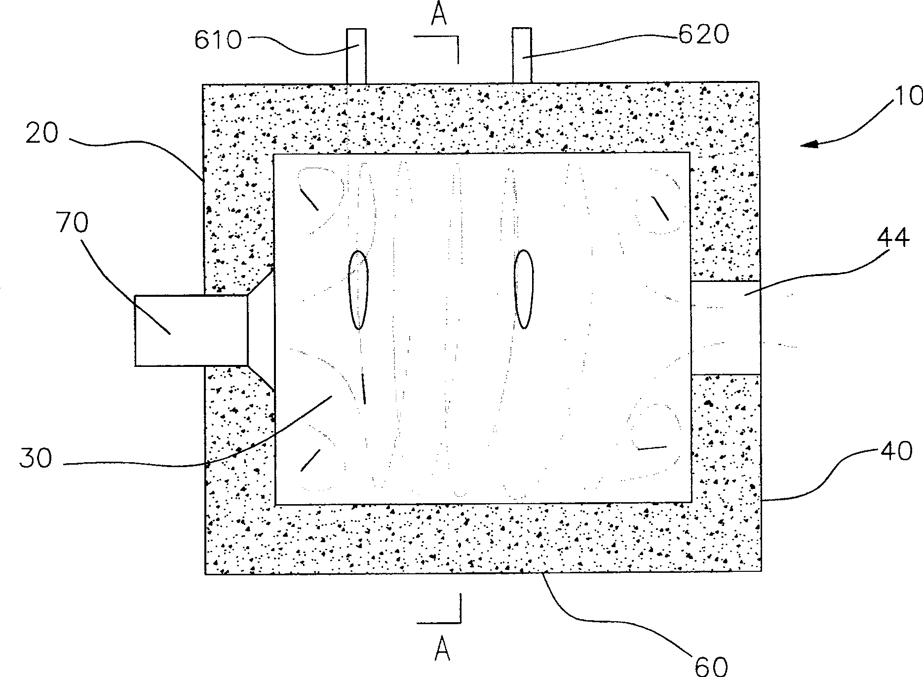
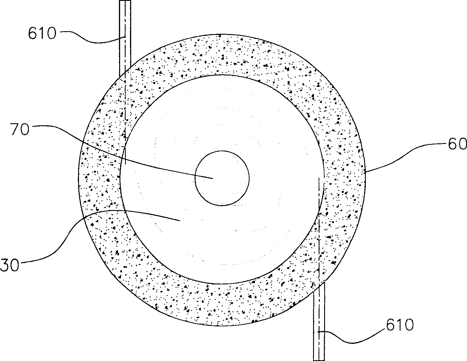
[0030] Please refer to figure 1 and figure 2 , the oxygen-lean emulsified coke slurry combustion device of the present invention is used to burn emulsified coke slurry, which includes a shell 10, an emulsified coke slurry burner 70, an oil burner and a gas burner (not shown).

[0031] The housing 10 is surrounded by a front wall 20 , a rear wall 40 , and a side wall 60 . The casing 10 is cylindrical, and a cylindrical combustion space 30 is formed inside the casing 10 . The vertical distance between the inner wall of the rear end wall 40 and the inner wall of the front end wall 20 is three times the inner diameter of the combustion space 30 .

[0032] The front end wall 20 of the casing is evenly provided with an emulsified coke burner 70, an oil burner and a gas burner, wherein the emulsified coke burner 70 is arranged at the center of the front end wall 20, and the oil burner and the gas burner are arranged at the emulsified coke burner. Below the slurry burner 70. The ...

Embodiment 2

[0043] This embodiment is similar to Embodiment 1, the difference is:

[0044] The vertical distance between the inner wall of the rear end wall 40 and the inner wall of the front end wall 20 is 4 times the inner diameter of the combustion space 30 .

[0045] The wind speed of the tangential wind delivered to the combustion space 30 by each tangential wind inlet is 28 m / s. Three groups of tangential air inlets with a total flow rate of 0.08 times the flow rate of the preheated air are arranged at intervals on the side wall of the casing 10 .

[0046] The atomization dispersion angle of the emulsified coke slurry ejected from the emulsified coke slurry burner is about 120 degrees.

[0047] The rotating direction of the swirling air formed by each group of tangential air inlets 610 and 620 is the same as that of the air injected by the swirling air distributor, both clockwise.

Embodiment 3

[0049] This embodiment is similar to Embodiment 1, the difference is:

[0050] The vertical distance between the inner wall of the rear end wall 40 and the inner wall of the front end wall 20 is 3.5 times the inner diameter of the combustion space 30 .

[0051] The wind speed of the tangential wind delivered by each tangential wind inlet to the combustion space 30 is 45 m / s. The total flow of tangential air delivered by each tangential air inlet to the combustion space 30 is 0.13 times of the preheated air flow.

[0052] A temperature sensor for measuring the temperature in the combustion space is provided on the casing 10 for monitoring and automatic control.


PUM


Abstract

This invention discloses a low-oxygen burning device of emulsification serum coke including front-end wall, back-end wall and side-wall shell in which there is the cylindraceous burning space. On the top of the front-end wall there are at least an emulsification serum coke burning device and an oil burning device or at least a gas burning device. The emulsification serum coke burning device sets a one-time air distribution intake which is used to carry the warm-up air to the burning space. The side wall of the shell is set interval with two or more tangential intakes which is used to carry the non-warm air that amounts to 0.06-0.1 times of the total warm-up air to the burning space. Each tangential intake includes even setting three or more tangential intakes. The vertical distance between the inside wall of the back-end wall and the inside wall of the front-end wall is 2 or 4 times of the diameter of the burning space. The invention emulsification serum coke burning device can burn with high efficiency under lower air coefficient.

Description

technical field [0001] The invention relates to thermal equipment, in particular to a combustion device using emulsified coke slurry as fuel. Background technique [0002] At present, the energy crisis has become a concern of people all over the world. The natural energy that can be used by human beings is decreasing, but the human demand for energy is increasing. Therefore, all countries in the world are adjusting their energy structure to save the existing energy to the greatest extent. At the same time, environmental pollution has also become the focus of attention of people all over the world in recent years. All countries in the world are working hard to adjust the industrial structure, develop and promote clean and low-pollution green energy. [0003] Therefore, people are constantly seeking new clean energy. Generally speaking, the relatively clean energy currently used by thermal equipment (such as various boiler equipment and kiln equipment) is mainly oil, natur...

Claims


Application Information

Patent Timeline
Patent Type & Authority Patents(China)
IPC IPC(8): F23C1/00F23C3/00F23C5/00F23C7/00F23D23/00F23L15/00F23L9/00
CPCY02E20/34
Inventor 常厚春李祖芹马革刘效洲
Owner GUANGZHOU DEVOTION THERMAL TECH
Why Eureka
Try Eureka