Caliper for a disk brake

A technology of disc brakes and brake calipers, which is applied in the direction of brake actuators, bearings for rotational motion, slack adjusters, etc., can solve the problems of large component stress, impracticality, and high cost of rolling bearings in the adjustment device, and achieve simplified assembly, Avoid stress concentrations, effects of low load levels

Inactive Publication Date: 2009-07-01
CONTINENTAL TEVES AG & CO OHG
View PDF6 Cites 3 Cited by
  • Summary
  • Abstract
  • Description
  • Claims
  • Application Information

AI Technical Summary

Problems solved by technology

Due to the high cost of rolling bearings, the increased complexity of the components and the necessity of hardening the respective working surfaces, this solution necessarily entails high manufacturing costs and is therefore considered impractical
In contrast, plain bearings with axially acting plain bearing plates are cost-effective, but cause high component stresses in the adjusting device due to the high bearing friction

Method used


Image

  • Caliper for a disk brake
  • Caliper for a disk brake
  • Caliper for a disk brake

Examples


Embodiment Construction

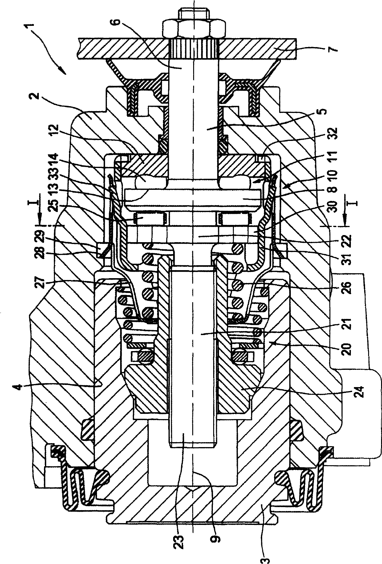
[0029] exist figure 1 The caliper 1 of a disc brake for a motor vehicle shown in , in particular comprises a housing 2 and a piston 3 which is movably arranged in a bore 4 for braking operation. In the case of a normal braking operation, the piston 3 is hydraulically movable. In order to realize the parking brake, a shaft 5 is provided which allows the piston 3 to be moved in the bore 4 by means of the actuating device 10 . The shaft 5 extends through an opening in the housing 2 with a shaft end 6 on which an actuating lever 7 is mounted. The actuating device 10 acts on the piston 3 by interposing an adjustment device 20 of variable length.

[0030] The actuating device 10 comprises a ramp structure 11 having a ramp element 12 fixed on said housing and a ramp element 13 rotatable relative to the ramp element 12 . The ramp element 13 is now integrally formed on the disk-shaped end 8 of the shaft 5 . A plurality of rolling bodies 14 are arranged between the ramp elements 12,...


PUM


Abstract

The invention relates to a brake caliper for a disc brake comprising a housing with a bore (4), a shaft (5) for actuation, two ramp elements (12, 13) rotatable relative to each other, There is an adjustment device (20) with a screw (21) and a thrust bearing (25) acting axially between the screw and the shaft, and a piston (3) movable in the axial direction is arranged in the hole, so The shaft is supported rotatably and axially movable. According to the invention, the object of the invention is achieved in that a toothing (30) is provided on the outer circumference of the screw (21) and a form-locking receptacle for this toothing (30) is provided, wherein the receptacle is connected to the housing (2) Connected in a non-rotatable manner and prevent the screw (21) from rotating. In another solution of the problem, a cap structure (35) is provided as a thrust bearing, the cap structure comprising a cap shell (36) with a concave curvature (38) and a cap pin with a convex curvature (39) (37).

Description

technical field [0001] The invention relates to a brake caliper for a disc brake, comprising a housing with a bore, a shaft for actuation, two ramp elements rotatable relative to each other, an adjustment device with a screw and on said screw a thrust bearing / axial support acting between the shaft, an axially movable piston is provided in the bore of the housing, the shaft is supported rotatably and axially movable and One shaft end of which passes through a casing opening, one of the two ramp elements is connected to the casing in a non-rotatable manner, and the other ramp element is connected to the shaft in a non-rotatable manner, The adjustment device is located between the shaft and the piston. Background technique [0002] Such a combined brake caliper for a disc brake of a motor vehicle is known from EP 0 403 635 B1. The caliper includes a housing having a bore in which a piston is movably disposed for braking operation. A shaft is mounted rotatably in the brake ho...

Claims


Application Information

Patent Timeline
Patent Type & Authority Patents(China)
IPC IPC(8): F16D65/14F16D65/56F16C17/08
Inventor R·派特里R·韦勒J·巴尔茨M·魏登韦伯
Owner CONTINENTAL TEVES AG & CO OHG
Why Eureka
Try Eureka