
Cutting mechanism for slender inner circular round pipe

A technology of cutting mechanism and inner ring, which is applied in the direction of thread cutting machine, turning equipment, thread cutting device, etc., can solve the problems of limited angular velocity, slow feed speed, short processing distance, etc., and achieves improved orientation and penetration, higher than The effect of high bore speed and machining accuracy

Inactive Publication Date: 2009-07-08
黄昌国
View PDF8 Cites 0 Cited by
  • Summary
  • Abstract
  • Description
  • Claims
  • Application Information

AI Technical Summary

Problems solved by technology

[0002] Existing slender circular inner circular pipes, especially pipe fittings with internal threads, such as internally threaded steel pipes are processed on lathes or tapped, because the stations during the processing of the circular pipes are partially clamped on On the fixture of the lathe, so during processing, when the tool is cutting, the relative eccentricity is high, the precision is low, and the processing distance is short. Occasionally, using this kind of lathe to process a long and slender inner circular tube, the tube is easily deformed elastically during processing, so the yield rate drops. Lathes are not applicable at all, and the feed speed of this lathe is slow and the work efficiency is low, so it is not suitable for mass production of slender inner circular tubes
And the production of the rifle of the gun barrel depends on the machining of the drawing machine. When the drawing machine is used to process the rifle, there must be certain requirements for the helix angle, and it must reach a certain value before it can be completed. The angular velocity of the bullet in the tube ejected from the bore

Method used


Image

  • Cutting mechanism for slender inner circular round pipe

Examples


Embodiment Construction

[0011] Attached below figure 1 Embodiments of the invention are illustrated:

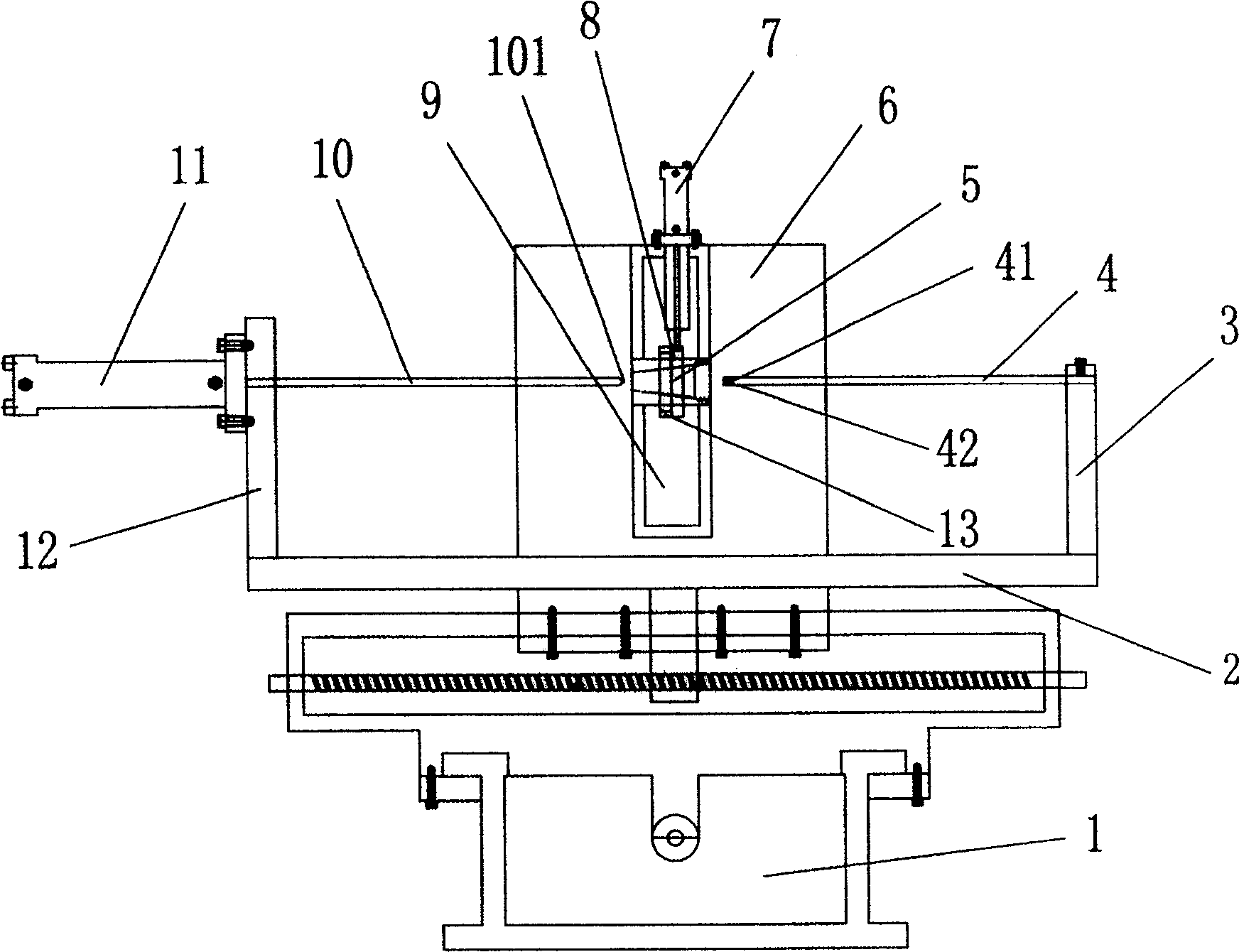
[0012] A cutting mechanism for a slender inner annular tube is set on the adjustable workbench 1 of the two-dimensional work coordinates (position on the horizontal plane), and the cutting mechanism for the slender inner annular tube is set on its workbench 1. There is a base plate 2, a wall board 12 is arranged on one side of the base board 2, and a first hydraulic cylinder 11 is fixed on the wall board 12, and the first hydraulic cylinder 11 is connected with a push rod 10; 3 is provided with a cutter bar 4, and the front end of the cutter bar 4 is provided with a cutting edge 41, and the ejector rod 10 and the cutter bar 4 are opposite or reversely centered; The rod 10 is oppositely aligned with the cutter rod 4; generally, the ejector rod 10 and the cutter rod 4 are oppositely aligned, such as figure 1 As shown, the notch 42 of the cutter bar 4 cooperates with the tip 101 of the ejector rod. H...


PUM


Abstract

A cutting mechanism for a slender inner circular tube, which is provided with a base plate on an adjustable workbench with two-dimensional work coordinates (position on the horizontal plane), and a wall plate is set on one side of the base plate, and the first hydraulic pressure is fixed on the wall plate. Cylinder, the first hydraulic cylinder is connected with the ejector rod; the other side of the base plate is provided with a tool holder, the tool holder is provided with a knife rod, the front end of the cutter rod is provided with a cutting edge, the ejector rod and the cutter rod are set opposite to each other, and the cutter rod passes through the top The rod is tightened; there is also a column on the backstage of the workbench, and a spindle box is fixedly connected to the column, and a second hydraulic cylinder is arranged on the spindle box. The spindle is located in the positioning circle, and the second hydraulic cylinder cooperates with the positioning ring on the spindle; The invention can be combined with numerical control technology, simple structure, scientific and reasonable, high processing precision, wide application, especially suitable for the processing of thinner and longer diameter round pipes, and has a wide range of applications in the field of military processing and civilian mechanical processing use.

Description

technical field [0001] The invention relates to a machine or device for processing snails in a round pipe, in particular to a cutting mechanism for processing a slender inner annular round pipe. Background technique [0002] Existing slender circular inner circular pipes, especially pipe fittings with internal threads, such as internally threaded steel pipes are processed on lathes or tapped, because the stations during the processing of the circular pipes are partially clamped on On the fixture of the lathe, so during processing, when the tool is cutting, the relative eccentricity is high, the precision is low, and the processing distance is short. Occasionally, using this kind of lathe to process a long and slender inner circular tube, the tube is easily deformed elastically during processing, so the yield rate drops. Lathe can not be applicable at all, and this lathe feed rate is slow, and work efficiency is low, is not suitable for the batch production of slender inner ...

Claims


Application Information

Patent Timeline
Patent Type & Authority Patents(China)
IPC IPC(8): B23B5/08B23B5/46B23G1/22B23Q3/00
Inventor 黄昌国
Owner 黄昌国
Learn More