
Leadless welding table

A technology of lead-free soldering stations and soldering nozzles, which is applied to welding equipment, soldering irons, electric heating devices, etc., can solve problems such as difficult temperature control, and achieve the effect of rapid transfer

Inactive Publication Date: 2009-07-08
SHENZHEN WENTENG HOT CONTROL ELECTRON
View PDF7 Cites 0 Cited by
  • Summary
  • Abstract
  • Description
  • Claims
  • Application Information

AI Technical Summary

Problems solved by technology

[0008] The technical problem to be solved by the present invention is to provide a very fast and very accurate lead-free soldering station for the above-mentioned defects in the prior art that the temperature is not easy to control

Method used


Image

  • Leadless welding table
  • Leadless welding table

Examples


Embodiment Construction

[0032] figure 1 It is a schematic diagram of the integrated soldering iron tip 9 in the embodiment of the present invention. As shown in the figure, the center of the soldering iron tip 9 is a rod-shaped first conductor 1 . The surface oxidized and insulated alloy wire 4 is wound on the first conductor 1 , one end is connected to the first conductor 1 , and the other end is connected to the second conductor 2 sheathed outside the first conductor 1 . In this way, the first conductor 1, the alloy wire 4 and the second conductor 2 form a heating circuit and are connected to a control circuit (not shown).

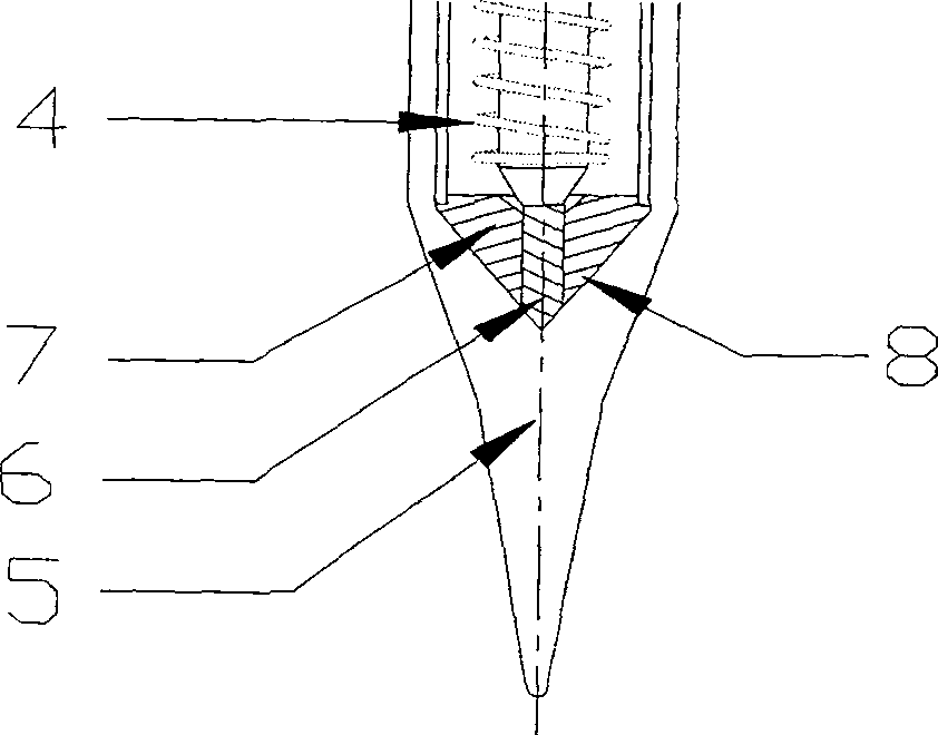
[0033] The third conductor 3 is a hollow cylinder, sheathed on the outside of the second conductor 2 and also surrounds the alloy wire 4 . figure 2 is an enlarged view of a working tip. Such as figure 2 As shown, the temperature sensing element 8 is connected in series between the first conductor 1 and the third conductor 3, forming a temperature measurement circuit and c...


PUM


Abstract

The invention relates to a lead-free soldering station, comprising a first conductor (1), a second conductor (2), a third conductor (3), an electric heating element (4), a temperature sensing element (8), a working welding tip ( 5) an integrated soldering iron tip (9); a handle connected to the soldering iron tip; and a control circuit. Wherein, the electric heating element (4) is connected in series between the first conductor (1) and the second conductor (2) to form a heating circuit and connected to the control circuit; the temperature sensing element (8) is connected in series at the first A temperature measurement circuit is formed between a conductor (1) and a third conductor (3) and is connected to the control circuit; there is a cavity at the tail of the working welding tip (5), and the electric heating element (4) and the temperature sensor Elements (8) are located in said cavity. The external shape of the temperature sensing element (8) is a cone, and its conical surface is close to the bottom surface of the cavity of the working welding tip (5). It has the advantages of fast heating and replenishment, accurate temperature measurement, and convenient replacement and disassembly.

Description

technical field [0001] The invention relates to an electric welding tool, more specifically, to a lead-free soldering station. Background technique [0002] The soldering station is a hand welding tool used for soldering in the processing of electronic products. In the previous similar products, most of its soldering iron tips adopt a detachable structure of heating core and working tip, and a sleeve is used to fix the two together. The temperature sensor is located inside the heater core. [0003] The problem of the soldering station with this structure is that the temperature sensor is far away from the working welding tip, which makes the detection of the temperature change of the welding tip not sensitive enough; the separable structure causes the loss of temperature transmission. For example, in applied patents such as CN200510123771.0, a refill-type soldering iron tip is used, and its temperature sensor is led to the welding tip through a wire. The temperature sensor...

Claims


Application Information

Patent Timeline
Patent Type & Authority Patents(China)
IPC IPC(8): B23K3/047B23K3/03
Inventor 孙勇
Owner SHENZHEN WENTENG HOT CONTROL ELECTRON
Learn More