Suspended carriage for wind energy facility, rotary connecting device for wind egergy facility, wind egergy facility, driving method for wind egergy facility

A rotary connector and wind energy technology, which is applied in the direction of wind power generators, wind power generation, and wind power engines in the same direction as the wind, can solve the problems of loss, wind energy facility downtime, large size, etc., and achieve the effect of easy monitoring and low cost

Inactive Publication Date: 2009-07-15
M伊勒
View PDF8 Cites 3 Cited by
  • Summary
  • Abstract
  • Description
  • Claims
  • Application Information

AI Technical Summary

Problems solved by technology

[0004] Due to the very large dimensions of conventional wind energy installations and their components, when damage occurs and individual components have to be replaced, two significant disadvantages appear, which lead to economic losses in the wind energy installation

Method used


Image

  • Suspended carriage for wind energy facility, rotary connecting device for wind egergy facility, wind egergy facility, driving method for wind egergy facility
  • Suspended carriage for wind energy facility, rotary connecting device for wind egergy facility, wind egergy facility, driving method for wind egergy facility
  • Suspended carriage for wind energy facility, rotary connecting device for wind egergy facility, wind egergy facility, driving method for wind egergy facility

Examples


Embodiment Construction

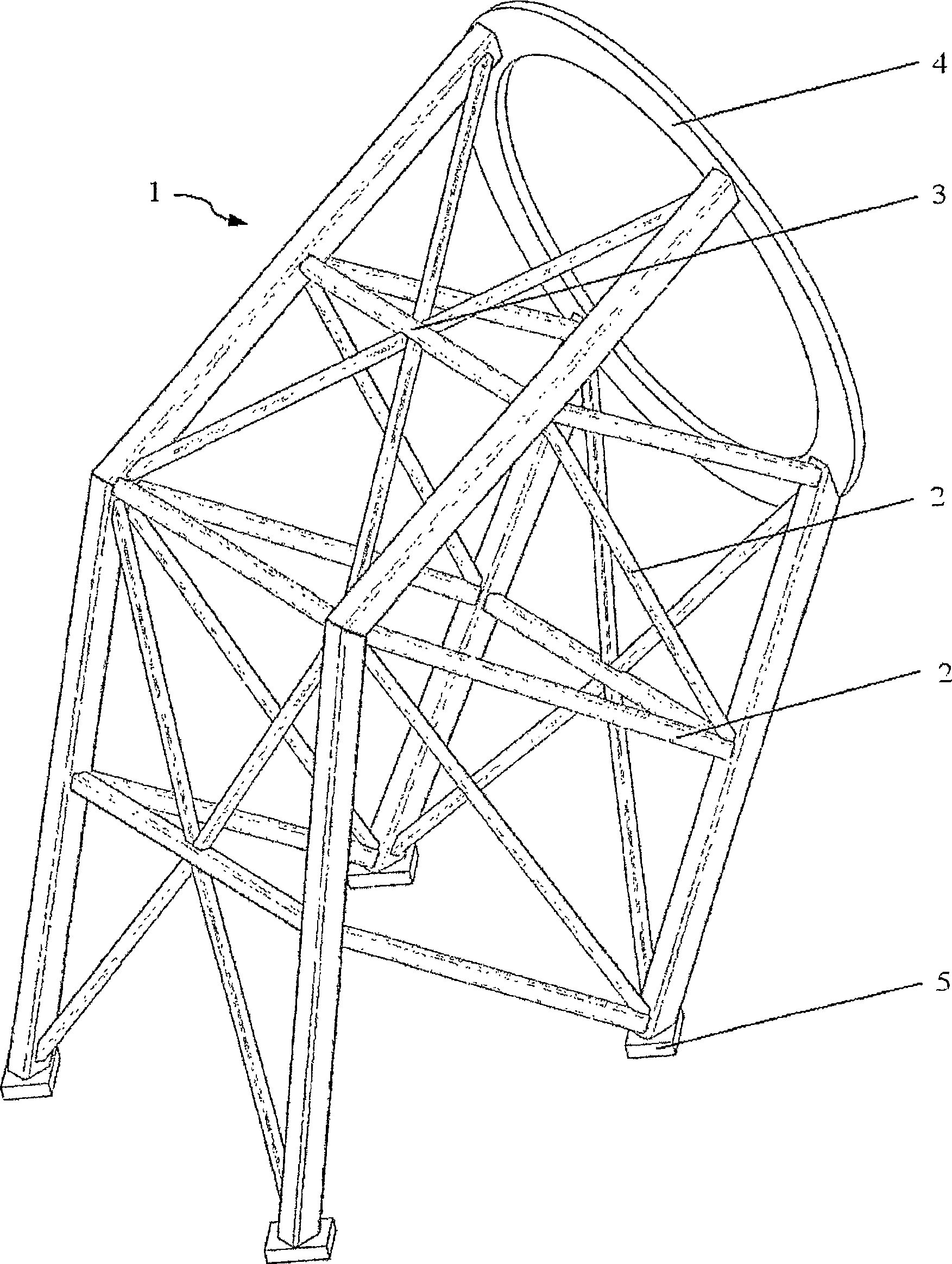
[0056] figure 1 An isometric view of the truss structure of a car 1 of the present invention is given. The truss structure consists of rods 2 which form nodes 3 at intersections. Its closing end is formed by a ring 4 in the direction of the rotor sleeve, not shown in the figure. On the side facing away from the ring 4 , the vertical load is distributed via the car-side coupling point 5 . The advantage of the truss member is: due to its versatility, it can provide a very wide variety of possible ways for the car 1 of the present invention, and can be stacked without any problem (unlike the "fishing technique" in toys of the prior art). "Contrast) for expansion.

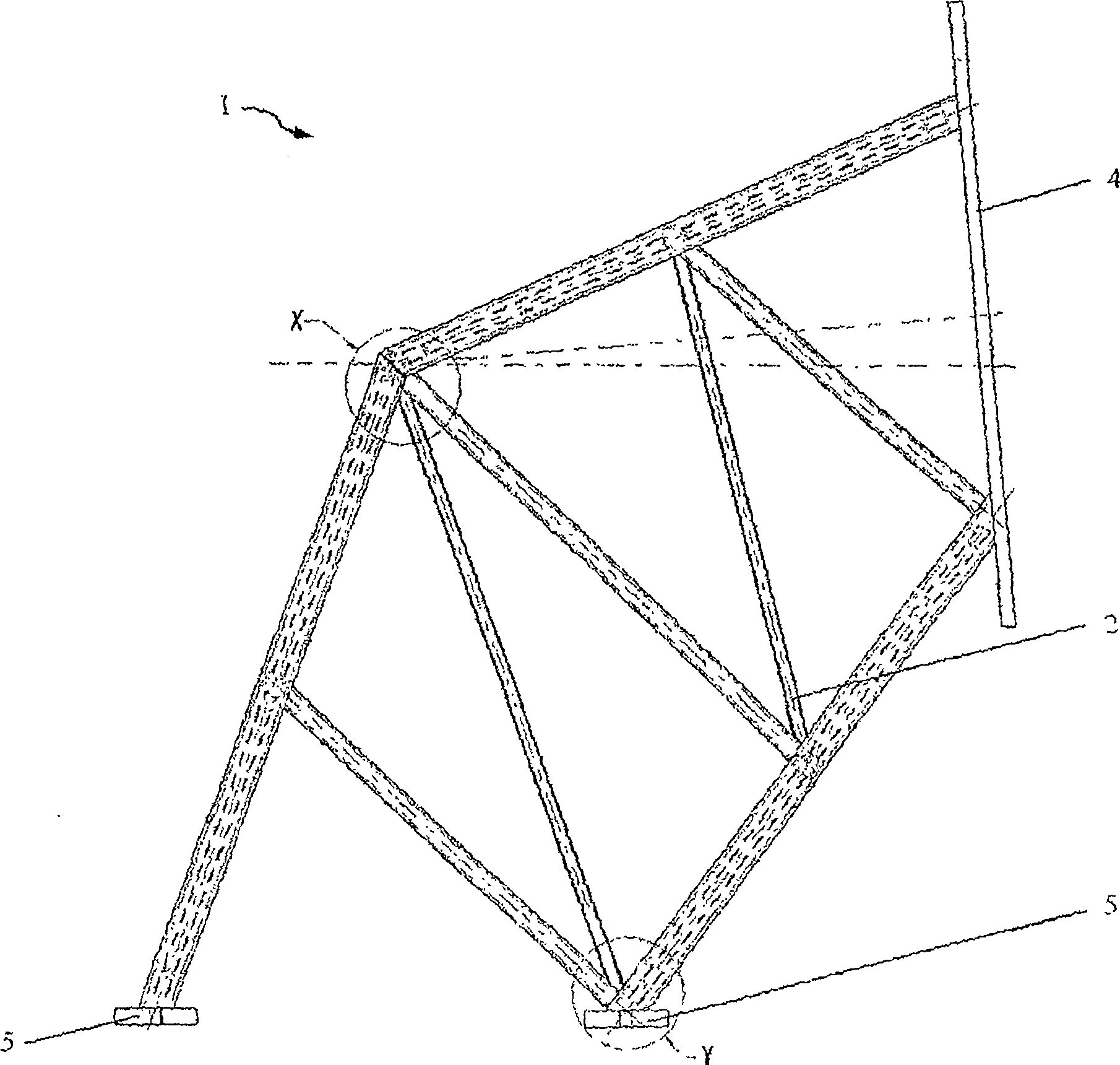
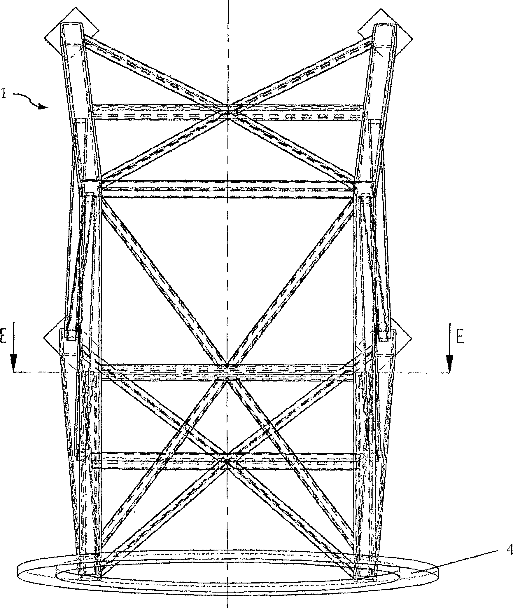
[0057] figure 2 and image 3 The front view and top view of the truss structure of the car 1 of the present invention are given in . It is obvious that the ring 4 does not have to be vertically oriented, but can also be arranged somewhat obliquely (inclined with respect to the rotor). A detailed view in X and Y...


PUM


Abstract

Provided are a gondola for a wind energy installation (WEA), a rotary coupling for a wind energy installation, a wind energy installation, and a driving method for a wind energy installation, wherein components common everywhere are used regardless of the wind energy installation are of any type, are easy to replace and / or are easy to manufacture in various places, therefore, they can be replaced at a low cost within a determined replacement interval, thereby minimizing the downtime waiting time of the wind energy installation of the present invention, therefore, by increasing The technical availability of the wind energy installation according to the invention optimizes its profitability.

Description

technical field [0001] The invention relates to: a car of a wind energy installation (WEA), a rotary connector of a wind energy installation, a wind energy installation, and a driving method of a wind energy installation. Background technique [0002] The development of wind energy utilization on land started about 20 years ago. Since then, wind energy installations, generally consisting of a tower and a gondola, have been continuously developed in terms of the transmission of the acting loads that occur to the tower and in the manufacturing technology. The car in which is supported on the tower. The car can be turned around a vertical axis by means of wind tracking bearings (i.d.R. single or double row ball slewing bearings), which track the wind direction and can be braked. It has a rotor sleeve, which is equipped with at least one rotor blade and is mounted so that it can rotate horizontally. Such a wind energy installation is described in the laid-open specification D...

Claims


Application Information

Patent Timeline
Patent Type & Authority Patents(China)
IPC IPC(8): F03D1/00F03D7/02
CPCY02E10/723Y02E10/728Y02E10/72
Inventor M·伊勒
Owner M伊勒
Why Eureka
Try Eureka