Power-feeding device and induction heating device
An electric power supply device and electric power technology are applied in the fields of induction heating devices and electric power supply devices, which can solve the problems of inability to improve the manufacturability, reduce the cost of the device, complicated circuit structure, etc., and achieve the improvement of the manufacturability, the easy device design and the cost reduction Effect
- Summary
- Abstract
- Description
- Claims
- Application Information
AI Technical Summary
Problems solved by technology
Method used
Image
Examples
no. 1 example
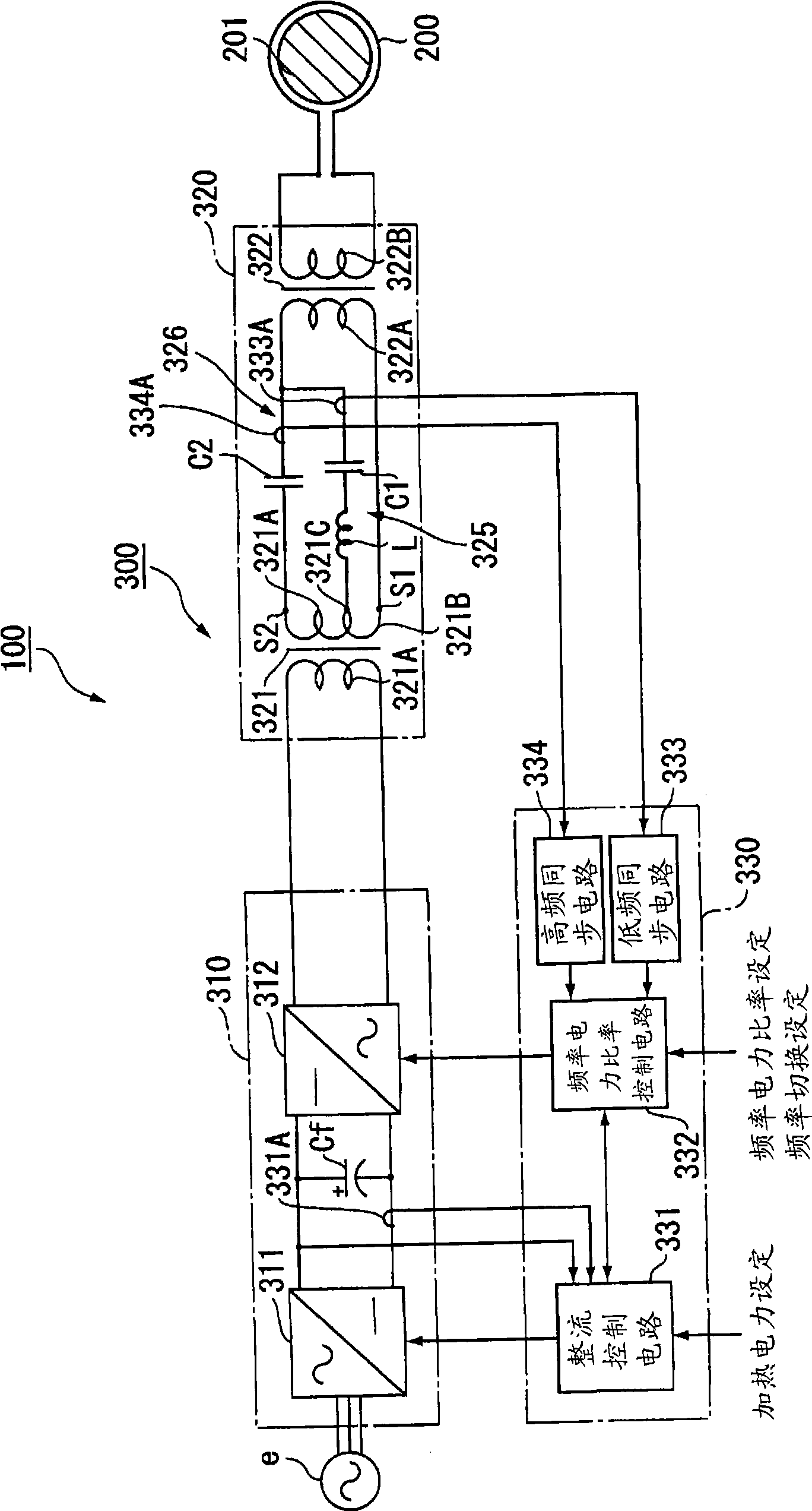
[0045] figure 1 It is a circuit diagram showing a schematic configuration of the induction heating device according to the first embodiment of the present invention.
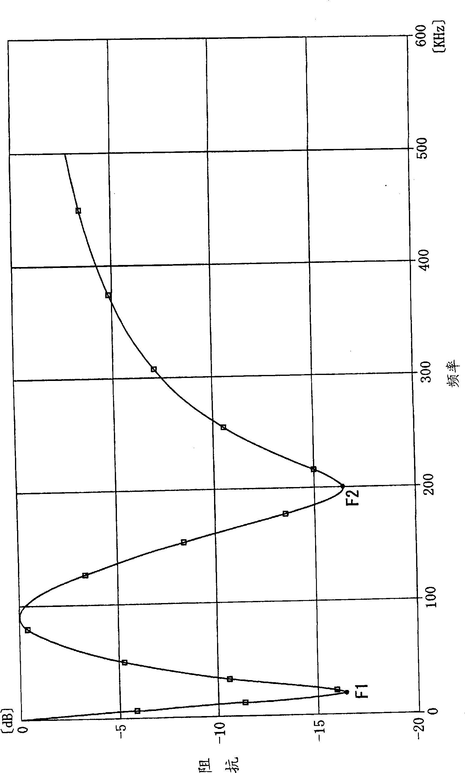
[0046] figure 2 is a graph showing the frequency characteristics of impedance in the matching circuit section.
[0047] (Structure of induction heating device)
[0048] exist figure 1 Among them, 100 is an induction heating device, and this induction heating device 100 has an induction heating coil 200 for inductively heating an object 201 to be heated, and a power supply device 300 for supplying power of different frequencies to the induction heating coil 200 for inductive heating .
[0049] The induction heating coil 200 is connected to a power supply device 300 . In this way, the induction heating coil 200 uses an equivalent inductance L0 of tens to hundreds of nH, for example, and is supplied with alternating currents of different frequencies from the power supply device 300 to inductively heat the o...
no. 2 example
[0084] (Structure of induction heating device)
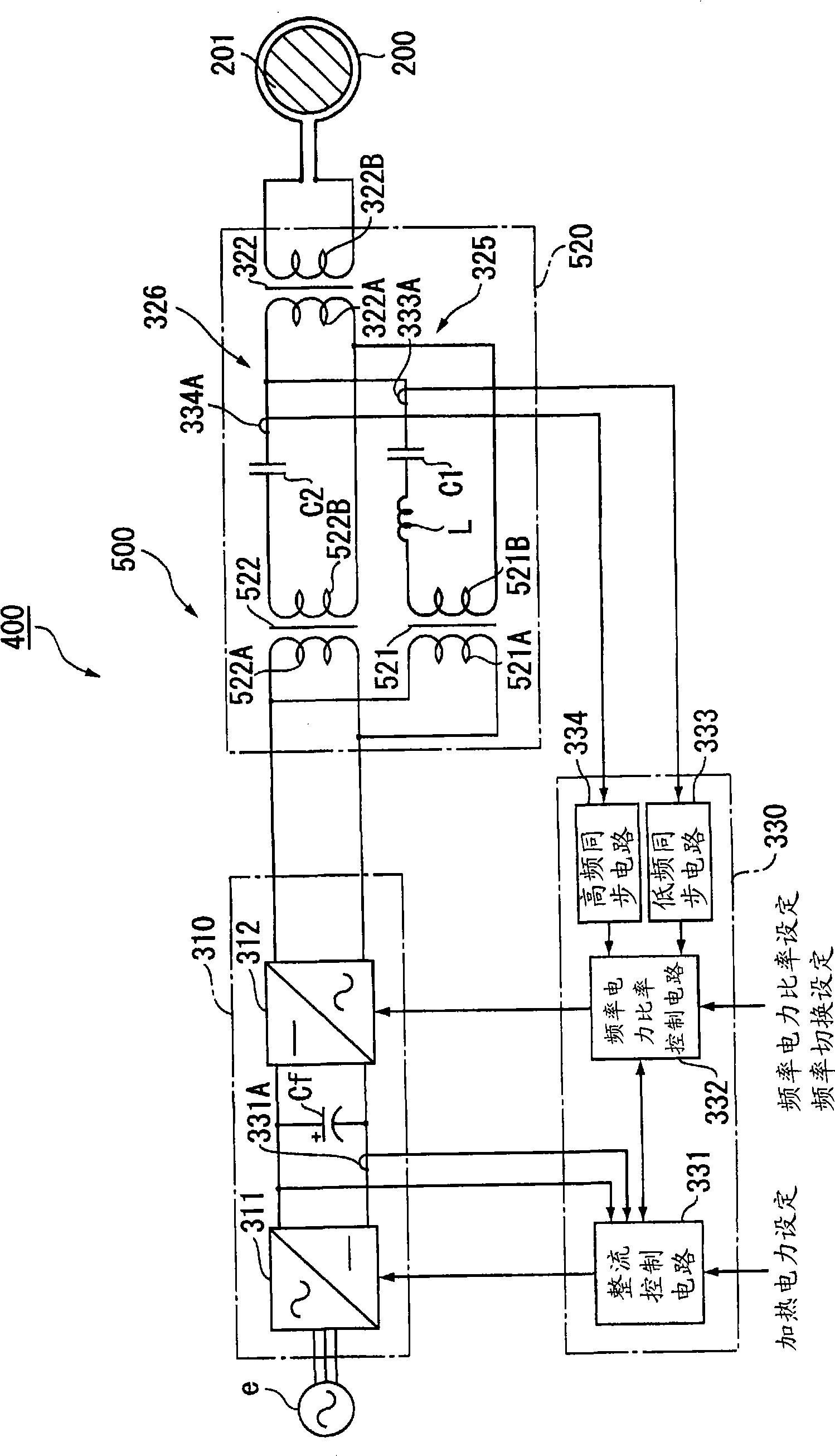
[0085] Next, a schematic configuration of an induction heating device according to a second embodiment of the present invention will be described with reference to the drawings. image 3 is a circuit diagram showing a schematic configuration of the induction heating device in the second embodiment.
[0086] exist image 3 Among them, 400 is an induction heating device, and the induction heating device 400 includes: figure 1 and figure 2 The induction heating device 100 of the first embodiment shown has the same induction heating coil 200 and a power supply device 500 for supplying electric power of a predetermined different frequency to the induction heating coil 200 for induction heating. Furthermore, the power supply device 500 includes the same oscillation circuit part 310 and control circuit part 330 as those of the induction heating device 100 of the first embodiment, and a matching circuit part 520 . Furthermore, in th...
no. 3 example
[0098] (Structure of induction heating device)
[0099] Next, a schematic configuration of an induction heating device according to a third embodiment of the present invention will be described with reference to the drawings. Figure 4 is a circuit diagram showing a schematic configuration of the induction heating device in the third embodiment.
[0100] exist Figure 4 Among them, 600 is an induction heating device, and the induction heating device 600 includes: figure 1 and figure 2 The induction heating device 100 of the first embodiment shown has the same induction heating coil 200 and a power supply device 700 for supplying electric power of a predetermined different frequency to the induction heating coil 200 for induction heating. Also, the power supply device 700 includes the same oscillation circuit section 310 , control circuit section 330 , and matching circuit section 720 as those of the induction heating device 100 of the first embodiment. Furthermore, in th...
PUM
 Abstract
Description
Claims
Application Information
 - R&D
- Intellectual Property
- Life Sciences
- Materials
- Tech Scout
- Unparalleled Data Quality
- Higher Quality Content
- 60% Fewer Hallucinations
Browse by: Latest US Patents, China's latest patents, Technical Efficacy Thesaurus, Application Domain, Technology Topic, Popular Technical Reports.
© 2025 PatSnap. All rights reserved.Legal|Privacy policy|Modern Slavery Act Transparency Statement|Sitemap|About US| Contact US: help@patsnap.com


