Intelligent double-frequency electronic label

An electronic label, intelligent technology, applied to the record carrier, instrument, computer parts and other directions used by the machine, can solve the problems of capital retention, large error, and the IC card is not well protected, and achieve the effect of stable working state.

Active Publication Date: 2009-10-28
刘明豪
View PDF4 Cites 0 Cited by
  • Summary
  • Abstract
  • Description
  • Claims
  • Application Information

AI Technical Summary

Problems solved by technology

[0007] 1. The accuracy of the source of system parameters cannot be guaranteed
[0008] 2. The update of system parameters lags behind, and the error is large
[0010] 4. Unable to provide a strong and convincing basis when there is an objection due to the split of the amount
[0011] 5. When an amount that cannot be split is generated, a large amount of funds will be stranded, affecting the normal operation and maintenance of the expressway
[0012] In addition, the ic card part of the existing structure is separated from the microwave circuit part, the ic card part is not well protected, and the working state is unstable
[0013] In short, in the current practical application of expressway toll collection, there is no marking device that can be put into practical use to record vehicle driving route information and is compatible with the requirements of existing toll collection characteristics.

Method used


Image

  • Intelligent double-frequency electronic label
  • Intelligent double-frequency electronic label
  • Intelligent double-frequency electronic label

Examples


Embodiment 1

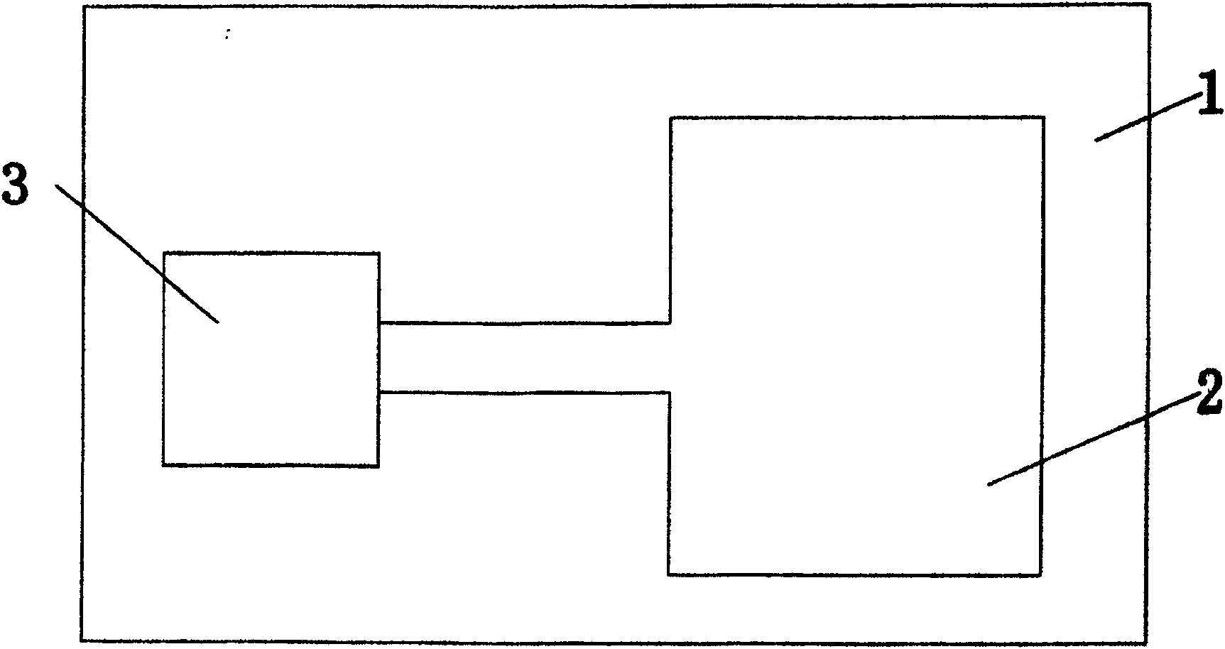
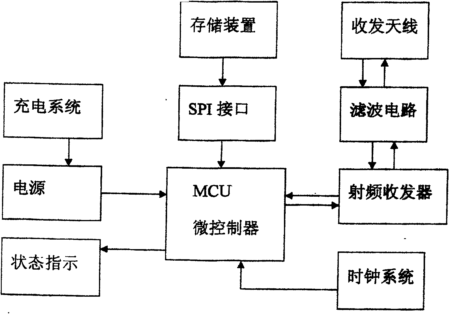
[0030] As shown in the figure, the present invention includes a circuit board 1, on which a microwave circuit, an IC antenna 2 and an IC chip 3 are arranged, wherein the microwave circuit includes a power supply circuit, a charging system, a status indicator, a storage device, and an SPI interface , microprocessor MCU circuit, transceiver antenna, filter circuit, radio frequency transceiver, clock system; wherein the power supply is connected to the main controller microprocessor MCU circuit, the storage device is connected to the microprocessor MCU circuit through the SPI interface, and the micro The processor MCU circuit is bidirectionally connected to the radio frequency transceiver, the radio frequency transceiver is bidirectionally connected to the filter circuit, the filter circuit is bidirectionally connected to the transceiver antenna, and the output terminal of the clock system circuit is connected to the microprocessor MCU circuit.

Embodiment 2

[0032] The present invention includes a circuit board 1, on which a microwave circuit, an IC antenna 2 and an IC chip 3 are arranged, wherein the microwave circuit includes a power supply circuit, a charging system, a status indicator, a storage device, an SPI interface, a microprocessor MCU Circuit, transceiver antenna, filter circuit, radio frequency transceiver, clock system; the power supply is connected to the main controller microprocessor MCU circuit, the storage device is connected to the microprocessor MCU circuit through the SPI interface, and the microprocessor MCU circuit is bidirectional Connected to the radio frequency transceiver, the radio frequency transceiver is bidirectionally connected to the filter circuit, the filter circuit is bidirectionally connected to the transceiver antenna, and the output end of the clock system circuit is connected to the microprocessor MCU circuit. In the present invention, the microwave circuit is arranged on one side of the circ...

Embodiment 3

[0034] As shown in the figure, the present invention includes a circuit board 1, on which a microwave circuit, an IC antenna 2 and an IC chip 3 are arranged, wherein the microwave circuit includes a power supply circuit, a charging system, a status indicator, a storage device, and an SPI interface , microprocessor MCU circuit, transceiver antenna, filter circuit, radio frequency transceiver, clock system; wherein the power supply is connected to the main controller microprocessor MCU circuit, the storage device is connected to the microprocessor MCU circuit through the SPI interface, and the micro The processor MCU circuit is bidirectionally connected to the radio frequency transceiver, the radio frequency transceiver is bidirectionally connected to the filter circuit, the filter circuit is bidirectionally connected to the transceiver antenna, and the output terminal of the clock system circuit is connected to the microprocessor MCU circuit.

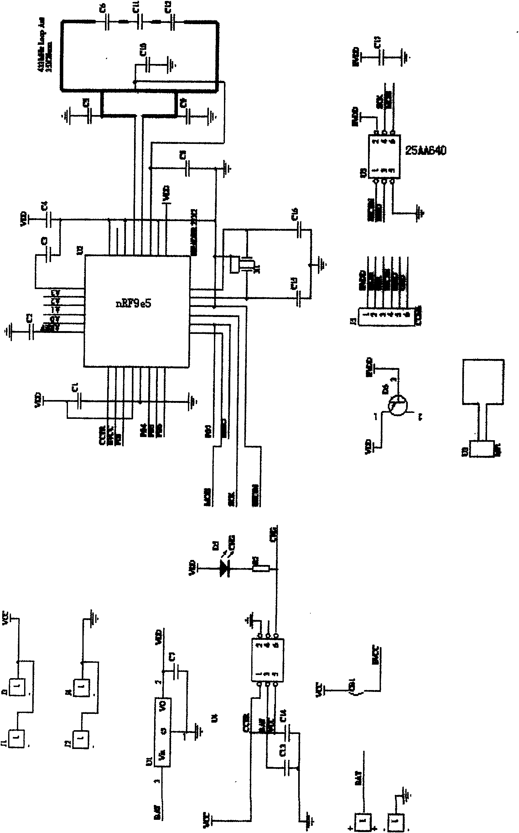
[0035] The frequency of the microw...


PUM


Abstract

The invention discloses an intelligent dual-frequency electronic labeling, which includes a circuit wafer, a microwave circuit, an IC antenna, and an IC chip, where in, the microwave circuit has a power supply circuit, a charging system, a status indicator, a storage device, a SPI interface, a microprocessor in a MCU circuit, dual mode antennas, a filter circuit, an RF transceiver, a clock system; the invention has the advantages of that: 1. two frequencies are supported in work. 2. the invention can still work when a module is broken. 3. multi-path information is recorded. 4. programming is supported. 5. the invention is compatible with an existing system. 6. an IC card part is well protected, work state is stable.

Description

technical field [0001] The invention relates to an intelligent dual-frequency electronic tag. Background technique [0002] At present, the multi-path identification technology commonly used in the market is an important topic in the field of intelligent transportation ITS. It is an important means to realize the intelligentization of vehicle driving and road management, and it is also an important basis for expressway tolls. Multi-path recognition technology is of great significance in providing traffic efficiency, improving road traffic environment and saving traffic energy because it can realize the function of vehicle driving route marking and make vehicle driving and road management intelligent and informatized. [0003] At home and abroad, the development and research of multi-path recognition technology is still in its infancy, and there are no related products on the market. The main research direction of multi-path identification technology is to realize the commun...

Claims


Application Information

Patent Timeline
Patent Type & Authority Patents(China)
IPC IPC(8): G06K19/077
Inventor 刘明豪
Owner 刘明豪
Why Eureka
Try Eureka