Ventilation device for internal combustion engine

A technology of a ventilator and an internal combustion engine, which is applied in the direction of engine lubrication, mechanical equipment, engine components, etc., can solve the problem of lubricating oil sucking into the combustion chamber, and achieve the effects of long passage path, improved removal effect, and low manufacturing cost.

Active Publication Date: 2009-11-18
WUXI KIPOR POWER CO LTD
View PDF4 Cites 0 Cited by
  • Summary
  • Abstract
  • Description
  • Claims
  • Application Information

AI Technical Summary

Problems solved by technology

Although this method avoids premature clogging of the air filter element, part of the oil mist still runs into the combustion chamber and is burned.
[0004] When the vacuum value in the intake manifold exceeds the specified range, such as after the air filter is blocked, the above solutions cannot solve the problem of lubricating oil being sucked into the combustion chamber

Method used


Image

  • Ventilation device for internal combustion engine
  • Ventilation device for internal combustion engine
  • Ventilation device for internal combustion engine

Examples


Embodiment Construction

[0023] Below the present invention will be further described in conjunction with the embodiment in the accompanying drawing:

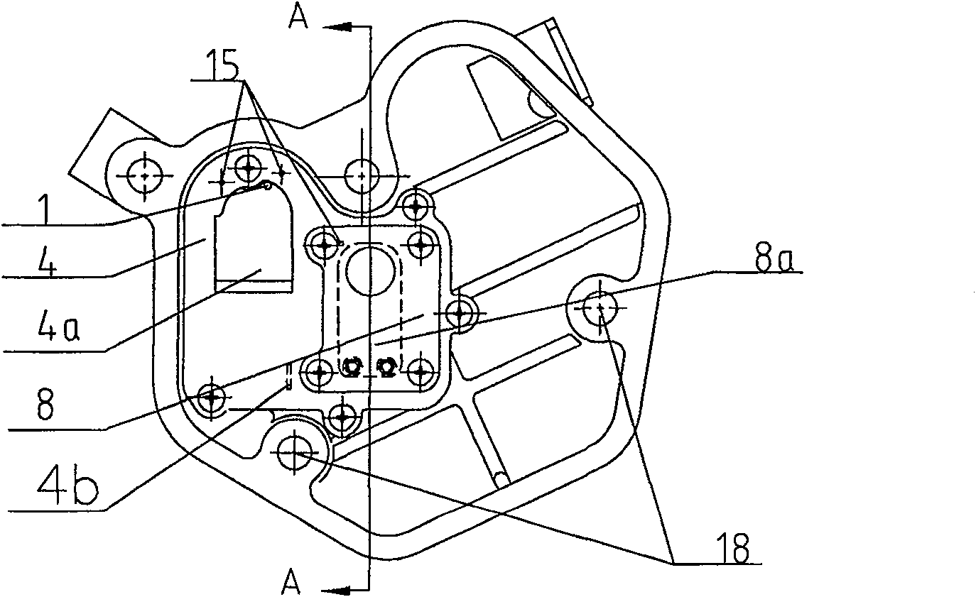
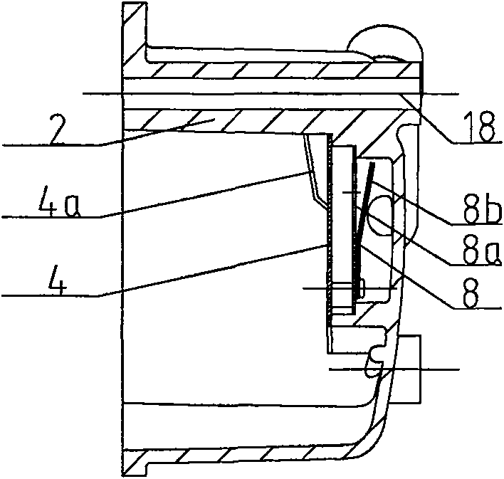
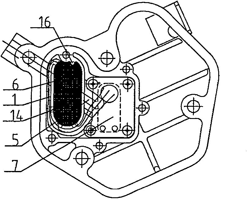
[0024] The present invention mainly consists of a cylinder head cover 1, a second cover plate 2, a rocker arm 3 for operating intake and exhaust valves, a first cover plate 4, a cavity 5, an oil-gas separation chamber 6, a control switch chamber 7, and a one-way valve component 8 (breathing shrapnel 8a, breathing sheet pressing plate 8b), pipeline system 9, cylinder head 10, intake manifold 11, filter screen 12, through hole 13, opening 14, oil drain hole 15, pillar 16, exhaust manifold 17, The cylinder head cover hole 18, the cavity 19 on the intake manifold and the rocker arm chamber 20 etc. are composed.

[0025] Such as Figure 1 ~ Figure 4 Shown: the present invention comprises a cylinder head cover 1, and a rocker arm 3 for operating intake and exhaust valves is included in the cylinder head cover 1. In the cylinder head 10 are provided an inta...


PUM


Abstract

The invention relates to a ventilation device of an internal combustion engine, which can prevent a large amount of oil mist from being sucked into a combustion chamber. The feature is that a first cover plate is arranged inside the cylinder head cover, and a cavity is formed by isolation of the first cover plate. The cavity includes an oil-gas separation chamber and a control switch room; the first cover plate is sealed on the oil-gas separation chamber; The second cover plate is fixed above, and a check valve component is installed on the second cover plate. The pipeline system is arranged in the control switch room, and the pipeline system communicates with the intake manifold on the cylinder head, and communicates with the control switch room. The invention can ensure a long passage path of oil and gas, improve the removal effect of oil mist, prevent excessive oil mist from entering the oil-gas separation chamber, and improve the safety performance of the entire internal combustion engine.

Description

technical field [0001] The invention relates to a ventilation device of an internal combustion engine, which can prevent a large amount of oil mist from being sucked into a combustion chamber, so as to improve the safety performance of the entire internal combustion engine. Background technique [0002] In a general internal combustion engine, the rocker arm that controls the intake and exhaust valves is located on the cylinder head. In order to keep the rocker arm parts in a sealed space, a hollow shell is fixed and sealed on the cylinder head. We call this hollow shell For the cylinder head cover, the space formed by the cylinder head cover and the cylinder head is called the rocker chamber. The rocker chamber is connected with the crankcase of the engine, so when the internal combustion engine is running, the temperature rises, and the oil mist in the crankcase fills the entire internal space, forming a certain pressure in the rocker chamber. [0003] In order to prevent...

Claims


Application Information

Patent Timeline
Patent Type & Authority Patents(China)
IPC IPC(8): F01M11/08F01M13/00F01M13/04
Inventor 肖亨琳
Owner WUXI KIPOR POWER CO LTD
Why Eureka
Try Eureka