
Test device and method of laser induced piston heat fatigue

An experimental device and thermal fatigue technology, applied in measurement devices, thermal analysis of materials, testing of machine/structural components, etc., can solve the problems of long experimental period, inability to test piston laser-induced thermal fatigue, uncontrollable heating area, etc. Short experimental period, easy parameter setting, good controllability

Inactive Publication Date: 2009-12-02
INST OF MECHANICS - CHINESE ACAD OF SCI
View PDF7 Cites 4 Cited by
  • Summary
  • Abstract
  • Description
  • Claims
  • Application Information

AI Technical Summary

Problems solved by technology

In general, the disadvantages of this type of test device are: the test period is relatively long, and the heating area is uncontrollable
However, their common disadvantage is that the laser-induced thermal fatigue test cannot be performed on the piston as a whole

Method used


Image

  • Test device and method of laser induced piston heat fatigue
  • Test device and method of laser induced piston heat fatigue
  • Test device and method of laser induced piston heat fatigue

Examples


Embodiment Construction

[0042] Below in conjunction with accompanying drawing and specific embodiment the present invention is described in further detail:

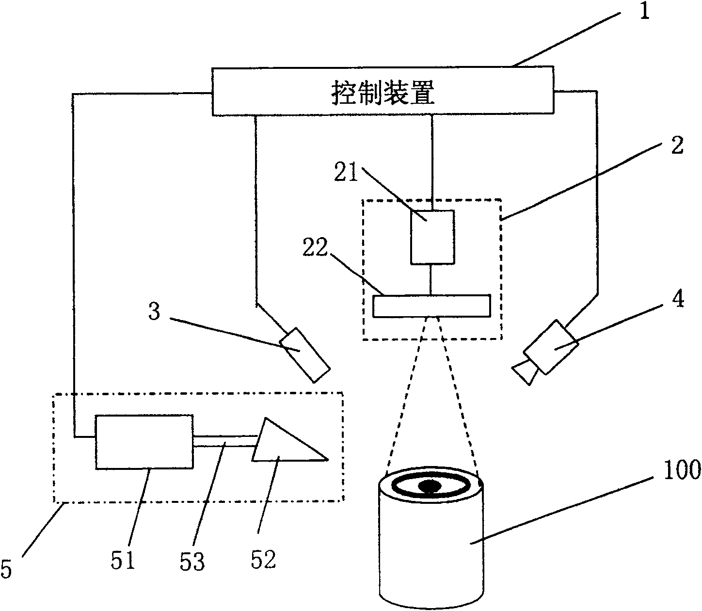
[0043] like figure 1 As shown, the laser-induced piston thermal fatigue experimental device of the present invention was made.

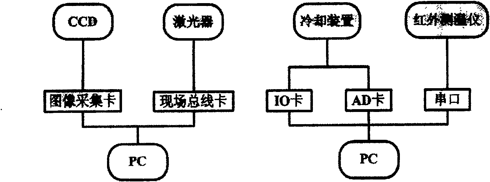
[0044] Wherein, the control device 1 includes an image acquisition card, an IO card, a PROFIBUS field bus card and two PCs.

[0045]The heating device 2 mainly includes a laser 21 and a beam shaper 22 . In this embodiment, the HL 3006D industrial Nd-YAG continuous laser produced by HAAS Company of Germany is used, and the maximum power is 3000W. The built-in Winlas software can control the laser 21 through the network cable, and also supports the development of control software based on the Profibus-DP protocol. The light output time and intensity of the laser 21 are controlled by the control device 1 . The laser device 21 that this embodiment selects supports Profibus-DP, the present invention adopts the linear ne...


PUM


Abstract

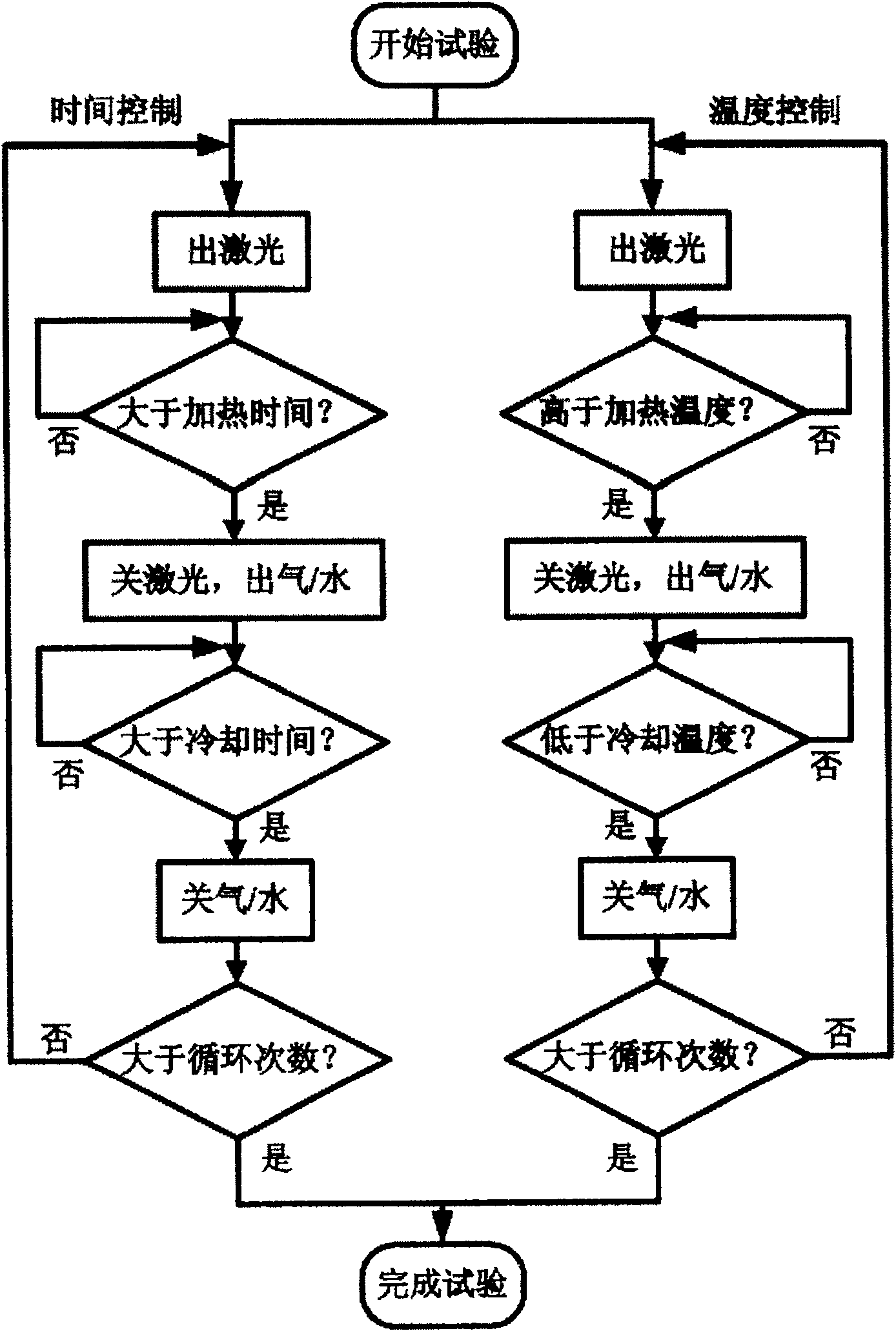
The invention discloses a piston thermal fatigue experiment device and method using laser as a heat source. The device includes: a bracket, a control device, a heating device, a temperature measuring device, a monitoring device and a cooling device; the heating device is composed of a laser and a beam shaping The laser emitted by the laser passes through the beam shaper and irradiates the piston surface vertically. The beam shaper transforms a beam of laser light emitted by the laser into a laser beam with multiple concentric ring-shaped spots. The method includes: a time control mode and a temperature control mode. Both control modes can realize piston high-cycle or low-cycle thermal fatigue simulation. The invention has the advantages of being able to simulate the temperature field distribution on the surface of the piston under actual working conditions, short experiment period and good controllability.

Description

technical field [0001] The invention relates to a thermal fatigue experimental device, in particular to an experimental device and an experimental method for piston thermal fatigue using laser as a heat source. Background technique [0002] At present, for the known technologies of piston thermal fatigue testing devices, many research institutions such as Zhejiang University have successively established thermal fatigue simulations using electromagnetic induction coils, quartz lamps, resistance heaters or gas flame injectors as heating methods. experiment platform. In general, the disadvantages of this type of testing device are: the experiment cycle is relatively long, and the heating area is uncontrollable. [0003] In the known technology, adopt laser to carry out the thermal fatigue test device of material sample, as document 1, M.Kutsuna, S.Fujita, Y.Sugita, et al.Thermal fatigue test for turbine housing by a pulseYAG laser[C ]. SPIE, 1999, 3888, disclosed in this doc...

Claims


Application Information

Patent Timeline
Patent Type & Authority Patents(China)
IPC IPC(8): G01N3/60G01N25/00
CPCG01M99/002
Inventor 虞钢周良宋宏伟郑彩云王立新宁伟健张金城李少霞王建伦庞铭刘兆王恒海
Owner INST OF MECHANICS - CHINESE ACAD OF SCI
Learn More