Method for controlling charging and discharging currents of adjuster for superconducting magnet

A current regulator, charge and discharge current technology, applied in the direction of conversion equipment with intermediate conversion to AC, etc., can solve the problems of easily damaged switching tubes, large switching losses, etc., to reduce switching losses, improve stability, and improve system performance Effect

Inactive Publication Date: 2009-12-16
INST OF ELECTRICAL ENG CHINESE ACAD OF SCI
View PDF3 Cites 0 Cited by
  • Summary
  • Abstract
  • Description
  • Claims
  • Application Information

AI Technical Summary

Problems solved by technology

Due to the large current passing through the superconducting magnet, it can be seen from the above switching action that the switching tube of the current source converter always needs to be turned on and off to realize charging and discharging when the current is large. , this way of charging and discharging not only makes the switching tube on the secondary side bear a large switching loss, but also easily damages the switching tube

Method used


Image

  • Method for controlling charging and discharging currents of adjuster for superconducting magnet
  • Method for controlling charging and discharging currents of adjuster for superconducting magnet
  • Method for controlling charging and discharging currents of adjuster for superconducting magnet

Examples


Embodiment Construction

[0023] The present invention will be further described below in conjunction with accompanying drawing and specific embodiment:

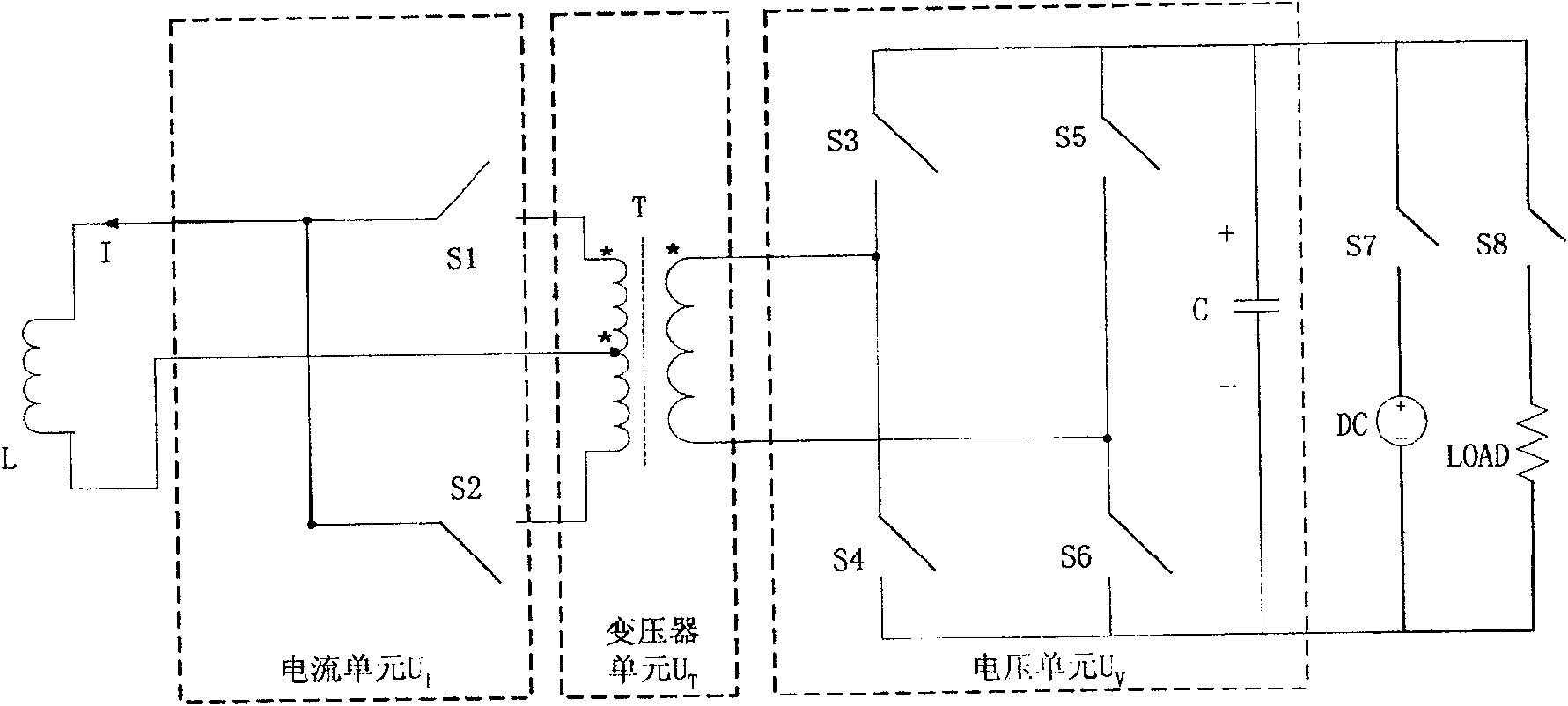
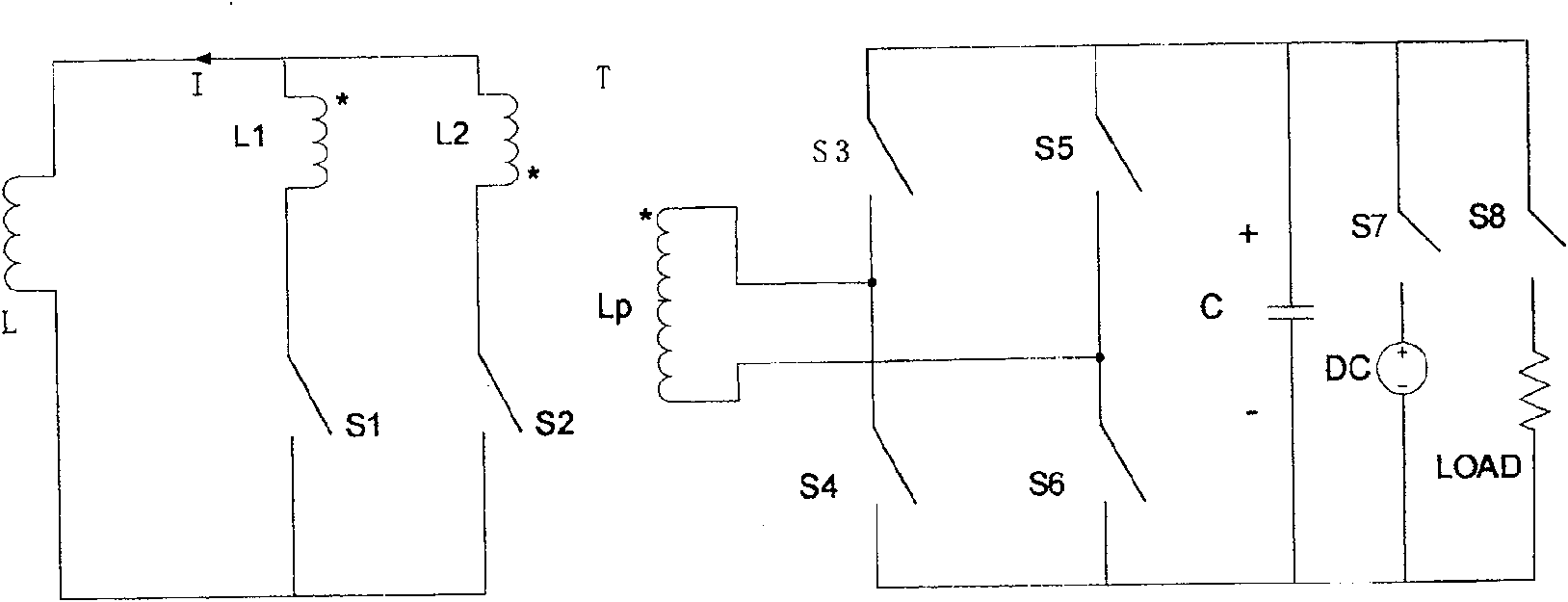
[0024] The main circuit diagram of patent 03137460.3 is as follows figure 1 as shown, figure 2 It is the schematic diagram of the main circuit of the patent 03137460.3.

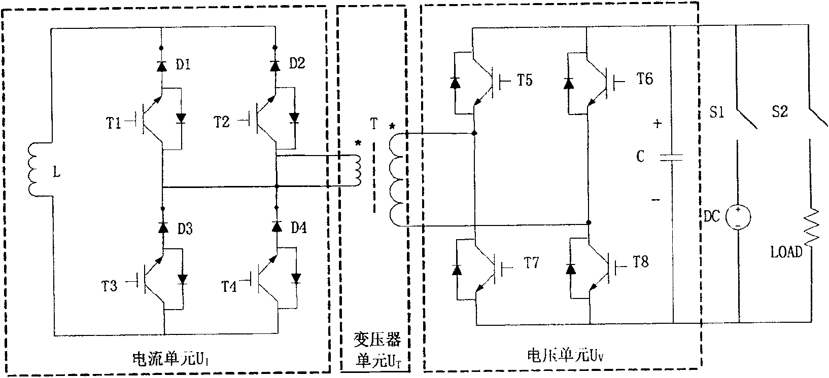
[0025] Such as figure 1 As shown, patent 03137460.3 consists of a voltage unit U V , Transformer unit U T , with the current unit U I It consists of three parts. Transformer unit U T for the current unit U I A transformer T with taps on the connected side. Voltage unit U V A DC side is composed of capacitor C connected in parallel with two bridge arms of the voltage source converter, the third switch S3 and the fourth switch S4 are connected in series to form a bridge arm of the voltage source converter, the fifth switch S5 and the sixth switch S6 The other bridge arm of the voltage source converter is formed in series, and the midpoint of the two bridge arms of the volt...


PUM


Abstract

A control method for a superconducting magnet charging and discharging current regulator. The voltage unit (UV) adopts a full-bridge phase-shift control method, and adjusts the power of charging and discharging through the relative phase shift between the leading bridge arm and the lagging bridge arm; The auxiliary potential provided by the current unit (UI) through the voltage unit (UV), the switching tubes of the two bridge arms of the current source converter first give a trigger signal to the switching tube of the bridge arm to be turned on at the moment of commutation, and then control the voltage The switching tube of the unit (UV) voltage source converter makes it generate commutation voltage on the primary side of the transformer (T). On the contrary, the current flowing through the switch is reduced; since the commutation voltage is in the same direction as the current flowing through the switch to be turned on, the current flowing through the switch is increased until the current flowing through the switch to be turned off is reduced to zero, Then turn off the switch tube. The invention can reduce the loss of the switch tube and improve the stability of the system.

Description

Technical field: [0001] The invention relates to a control method for a superconducting magnet charging and discharging current regulator, in particular to an auxiliary potential phase-shifting control method for the current regulator. Background technique: [0002] The characteristics of zero resistance and high current-carrying capacity under a strong magnetic field make superconducting magnets widely used, especially large magnets used to generate strong magnetic fields in high-energy physics experiments. Superconducting magnets have almost replaced all conventional magnets with large volume and high power consumption; at the same time, with the development of superconducting power technology, especially micro-superconducting energy storage, it has been commercialized abroad and is widely used to improve power quality and increase Power system stability, etc., these have made superconducting magnets have been used in unprecedented applications. [0003] The general opera...

Claims


Application Information

Patent Timeline
Patent Type & Authority Patents(China)
IPC IPC(8): H02M3/28
Inventor 赵彩宏李顺郭文勇肖立业林良真余运佳
Owner INST OF ELECTRICAL ENG CHINESE ACAD OF SCI
Why Eureka
Try Eureka