
Plasma uniformity control by gas diffuser

A gas dispersion and plasma technology, applied in electrical components, gaseous chemical plating, coatings, etc., can solve problems such as poor center thickness uniformity

Active Publication Date: 2009-12-30
APPLIED MATERIALS INC
View PDF11 Cites 5 Cited by
  • Summary
  • Abstract
  • Description
  • Claims
  • Application Information

AI Technical Summary

Problems solved by technology

Larger substrates have worse center thickness uniformity issues

Method used


Image

  • Plasma uniformity control by gas diffuser
  • Plasma uniformity control by gas diffuser
  • Plasma uniformity control by gas diffuser

Examples


Embodiment Construction

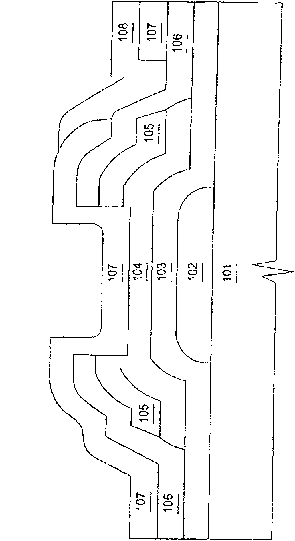
[0092] The present invention generally provides a gas distribution assembly for providing gas delivery within a processing chamber. The present invention will be described below in terms of a plasma-enhanced chemical vapor deposition system for processing large area substrates, such as that available from Applied Materials, Inc. Division AKT of Santa Clara, California, USA ( PECVD) system. However, it must be understood that the present invention can be applied to other configurations (such as etching systems), other chemical vapor deposition systems, and other systems that require the distribution of gas within the processing chamber, including systems that process circular substrates.

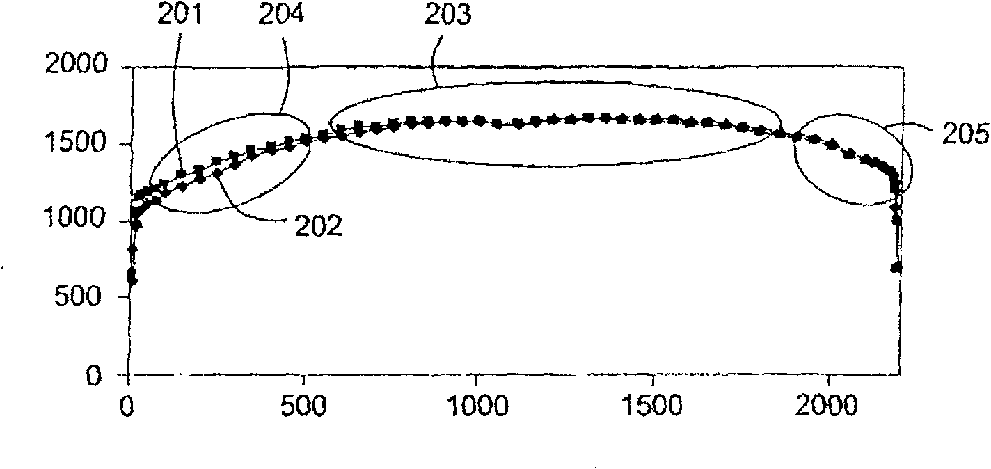
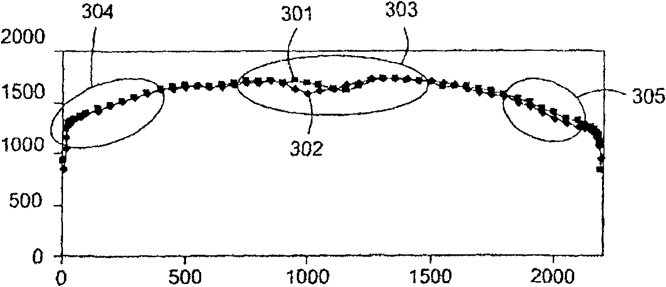
[0093] For silicon nitride films, the central thickness uniformity issue has been addressed by varying the size and / or distribution of the cathode cavities on the downstream surface of the PECVD gas diffuser plate. The cathode cavity enhances plasma ionization in the PECVD chamber. Because ...


PUM

PropertyMeasurementUnit
diameteraaaaaaaaaa
diameteraaaaaaaaaa
surface areaaaaaaaaaaa

Abstract

Embodiments of a gas distribution plate for distributing gas in a processing chamber are provided. In one embodiment, a gas distribution assembly for a plasma processing chamber comprises a diffuser plate with gas passages passing between its upstream and downstream sides and hollow cathode cavities at the downstream side of the gas passages. The downstream side of the diffuser plate has a curvature to improve the thickness uniformity and film property uniformity of thin films deposited by PECVD, particularly SiN and amorphous silicon films. The curvature is preferably described by an arc of a circle or ellipse, the apex thereof located at the center point of the diffuser plate. In one aspect, the hollow cathode cavity volume density, surface area density, or the cavity density of the diffuser increases from the center of the diffuser to the outer edge. Methods for manufacturing such a diffuser plate are also provided.

Description

technical field [0001] Embodiments of the invention generally relate to a gas distribution plate assembly and a method for distributing a gas in a processing chamber. Background technique [0002] Liquid crystal displays or flat panels are commonly used in active matrix displays such as computer and television screens. Plasma enhanced chemical vapor deposition (PECVD) is generally used to deposit thin film layers on a substrate such as a transparent substrate for flat panel displays or a semiconductor wafer. PECVD is typically accomplished by introducing a precursor gas or gas mixture into a vacuum chamber containing the substrate. The precursor gas or mixture gas is typically directed downward through a diffuser plate adjacent to the top of the chamber. A precursor gas or gas mixture within the chamber is energized (eg, excited) into a plasma by applying RF power to the chamber from one or more radio frequency (RF) sources coupled to the chamber. The energized gas or gas...

Claims


Application Information

Patent Timeline
Patent Type & Authority Patents(China)
IPC IPC(8): C23C16/455C23C16/509
CPCC23C16/4583H01J37/3244H01J2237/3325
Inventor 崔寿永朴范秀J·M·怀特R·L·蒂纳
Owner APPLIED MATERIALS INC
Features
  • Generate Ideas
  • Intellectual Property
  • Life Sciences
  • Materials
  • Tech Scout
  • Unparalleled Data Quality
  • Higher Quality Content
  • 60% Fewer Hallucinations
Learn More